

The Lightning Protection System (LPS) shall be executed by a specialised and experienced agency.
The complete system design, drawings, calculations and technical details shall be submitted to the Consultant / Client for approval prior to execution.
The proposed LPS shall be properly interconnected with the existing Lightning Protection System available at site.
The quantities indicated are tentative and are provided for tender purpose only. Any additional items/components required for proper functioning and completeness of the LPS shall be deemed to be included in the contractor’s scope at no extra cost, and the system shall be complete in all respects.
SCOPE OF WORK
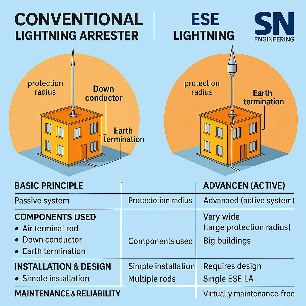
Supply, Installation, Testing and Commissioning (SITC) of Conventional Type Lightning Protection System as per IEC 62305, latest National Building Code (NBC) of India and applicable standards.
The scope shall include all accessories, fasteners, clamps, screws, bolts, nuts, supports, testing, documentation and all items necessary to make the system fully functional and complete in all respects.
All components shall conform to IEC 62561, EN, VDE and other applicable international standards.
TECHNICAL SPECIFICATION
1. Air Termination Conductor
SITC of 8 mm diameter solid Aluminium Conductor for horizontal air termination on terrace/roof.
Tested as per IEC 62561-2.
Testing shall be conducted in Government-approved / accredited third-party laboratory.
The conductor shall meet the requirements of IS / IEC 62305.
2. Terrace Conductor Holder (Flat Roof)
Terrace holder made of frost-resistant concrete.
Minimum weight: 1 kg per holder.
Installation spacing: 1 meter c/c.
Suitable for flat roof applications.
3. Universal Clamp
Universal clamp made of stainless steel.
Tested as per applicable standards.
Suitable for cross connections, T-connections and interconnections.
4. Expansion Piece
Expansion piece to be provided at every 20 meters.
Made of aluminium conductor.
Tested as per applicable standards.
Rated for 100 kA lightning current.
5. Parallel Connector
Parallel connector made of stainless steel.
Tested as per applicable standards.
Used for interlinking expansion piece and 8 mm aluminium conductor.
6. Parapet Conductor Holder
Supply of roof conductor holder for parapet walls:
Polyamide conductor holder
With M8 female thread / 7 mm diameter
M8 screw for fixing the conductor holder
Weather and temperature resistant from –35°C to +90°C
Installation spacing: 1 meter
Tested as per IEC 62561
Suitable for:
Round conductors Rd 8–10 to Rd 16
Flat conductors FL30
Including 2 Nos. M8 × 20 mm hexagonal bolts, high-grade stainless steel
TEMPORARY POWER & LIGHTING (LUMP SUM)
Lump sum charges for distribution, installation, operation and maintenance of temporary power supply and lighting for all agencies at site, including:
Tube lights / flood lights
Industrial sockets with MCB
Plug tops
ELCB and all required safety devices
The system shall ensure safe, continuous and uninterrupted power supply throughout the project duration.
The scope includes:
All floors
Shafts
Project office
Storage areas
Plug points and light fittings
The contractor shall also provide continuous maintenance of the temporary power distribution system for the entire duration of the project.
DRAWINGS & APPROVALS
Preparation of detailed shop drawings
Submission and revision until approval from Consultant / Client
Approval of drawings and works from Electrical Inspector
Obtaining charging permissions from CEIG / concerned authorities
MS TRENCH / SHAFT COVERS
SITC of MS covers for electrical trenches / shafts, fabricated from:
6 mm thick MS chequered plates
With suitable MS angle stiffeners
Proper lifting arrangement as per approved drawings
Painting system:
Primer coat
Red oxide coat
Two coats of finishing paint (approved colour)
SYSTEM STUDIES (THIRD-PARTY)
Arranging system studies for the complete electrical distribution system (Full SLD) through a competent third-party agency, including submission of reports in approved formats.
Credentials of testing agency to be submitted and approved by Consultant
(Efficienergy Consulting or equivalent approved agency).
Studies to include:
Arc-Flash Study
Load Flow Study
Short Circuit Study
Relay Coordination Study
Relay coordination and calibration shall be carried out as per approved PDC report.
FIRE SEALANT WORKS
A. Fire Sealant for Walls
Supply and installation of expanding firestop foam
Minimum 2 hours fire rating
Tested as per FM Approval Class No. 4990
Applicable for horizontal and vertical openings in floors/walls
Installation by trained applicators
Inclusive of packing materials
Aesthetic, water-tight finish
Wall thickness: 200 mm
Quantity based on actual gap size
B. Fire Sealant for Shafts
Supply and installation of Fire Barrier Mortar CP 636
Minimum 2 hours fire rating
Tested as per FM Approval Class No. 4990
For service shafts through fire-rated floors and walls
Minimum thickness: 70 mm
Product shall bear UL & FM approval marking
Inclusive of all materials and application
Aesthetic, water-tight finish
Quantity based on actual gaps