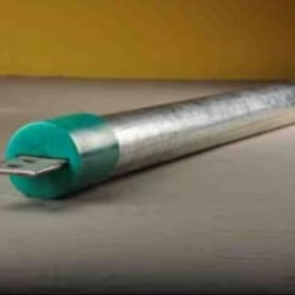
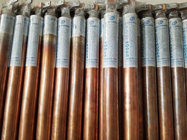
GI Earthing Vs Copper EarthingAs per IS 3043, the resistance of Plate electrode to earth (R) = (r/A) X under root(P/A).Where r = Resistivity of Soil Ohm-meter.A=Area of Earthing Plate m3.The resistance of Pipe electrode to earth (R) = (100r/2πL) X loge (4L/d).Where L= Length of Pipe/Rod in cmd=Diameter of Pipe/Rod in cm.The resistivity of the soil and the physical dimensions of the electrode play important role of resistance of Rod with earth.The material resistivity is not considered important role in earth resistivity.Any material of given dimensions would offer the same resistance to earth. Except the sizing and number of the earthing conductor or the protective conductor.
Pipe Earthing Vs Plate EarthingSuppose Copper Plate having of size 1.2m x 1.2m x 3.15mm thick. soil resistivity of 100 ohm-m, The resistance of Plate electrode to earth (R)=( r/A)X under root(π/A) = (100/2.88)X(3.14/2.88)=36.27 ohmNow, consider a GI Pipe Electrode of 50 mm Diameter and 3 m Long. soil resistivity of 100 Ohm-m, The resistance of Pipe electrode to earth (R) = (100r/2πL) X loge (4L/d) = (100X100/2X3.14X300) X loge (4X300/5) =29.09 Ohm.From the above calculation the GI Pipe electrode offers a much lesser resistance than even a copper plate electrode.As per IS 3043 Pipe, rod or strip has a much lower resistance than a plate of equal surface area.
Length of Pipe Electrode and Earthing Pit
The resistance to earth of a pipe or plate electrode reduces rapidly within the first few feet from ground (mostly 2 to 3 meter) but after that soil resistivity is mostly uniform.
After about 4 meter depth, there is no appreciable change in resistance to earth of the electrode. Except a number of rods in parallel are to be preferred to a single long rod.
Amount of Salt and Charcoal (more than 8Kg)
To reduce soil resistivity, it is necessary to dissolve in the moisture particle in the Soil. Some substance like Salt/Charcoal is highly conductive in water solution but the additive substance would reduce the resistivity of the soil, only when it is dissolved in the moisture in the soil after that additional quantity does not serve the Purpose.
5% moisture in saltreduces earth resistivity rapidly and further increase in salt content will give a very little decrease in soil resistivity.
The salt content is expressed in percent by weight of the moisture content in the soil. Considering 1M3 of Soil, the moisture content at 10 percent will be about 144 kg. (10 percent of 1440 kg). The salt content shall be 5% of this (i.e.) 5% of 144kg, that is, about 7.2kg.
Amount of Water Purring
Moisture content is one of the controlling factors of earth resistivity. Above 20 % of moisture content, the resistivity is very little affected. But below 20% the resistivity increases rapidly with the decrease in moisture content.
If the moisture content is already above 20% there is no point in adding quantity of water into the earth pit, except perhaps wasting an important and scarce national resource like water.
Length Vs Diameter of Earth Electrode
Apart from considerations of mechanical strength, there is little advantage to be gained from increasing the earth electrode diameter with the object in mind of increasing surface area in contact with the soil.
The usual practice is to select a diameter of earth electrode, which will have enough strength to enable it to be driven into the particular soil conditions without bending or splitting. Large diameter electrode may be more difficult to drive than smaller diameter electrode.
The depth to which an earth electrode is driven has much more influence on its electrical resistance characteristics than has its diameter.
Maximum allowable Earth resistanceMajor power station = 0.5 OhmMajor Sub-stations = 1.0 OhmMinor Sub-station = 2 OhmNeutral Bushing = 2 OhmService connection = 4 OhmMedium Voltage Network = 2 OhmL.T.Lightening Arrestor = 4 OhmL.T.Pole = 5 OhmH.T.Pole = 10 OhmTower = 20-30 Ohm
Treatments to for minimizing Earth resistanceRemove Oxidation on joints and joints should be tightened.Poured sufficient water in earth electrode.Used bigger size of Earth Electrode.Electrodes should be connected in parallel.Earth pit of more depth & width- breadth should be made.
Originally published at Electrical Notes and Articles
Related electrical guides & articles
Premium Membership
Premium membership gives you an access to specialized technical articles and extra premium content (electrical guides and software).
GET PREMIUM NOW ⚡
About AuthorJignesh ParmarJignesh Parmar has completed M.Tech (Power System Control) , B.E(Electrical). He is member of Institution of Engineers (MIE), India. Membership No:M-1473586.He has more than 13 years experience in Transmission -Distribution-Electrical Energy theft detection-Electrical Maintenance-Electrical Projects (Planning-Designing-Technical Review-coordination -Execution). He is Presently associate with one of the leading business group as a Deputy Manager at Ahmedabad, India. He has published numbers of Technical Articles in "Electrical Mirror", "Electrical India", "Lighting India", "Industrial Electrix"(Australian Power Publications) Magazines. He is Freelancer Programmer of Advance Excel and design useful Excel base Electrical Programs as per IS, NEC, IEC, IEEE codes. He is Technical Blogger and Familiar with English, Hindi, Gujarati, French languages. He wants to Share his experience & Knowledge and help technical enthusiasts to find suitable solutions and updating themselves on various Engineering Topics.
43 Comments
Sumit
MAY 24, 2018
Which type of earthing system we should follow for industrial projects in india (TN-S, TNC-S or TT)?
(reply)
Lakshminarayana Rao
APR 28, 2018
generally how to calculate the earthing conductor strip its dimensions and length for different types of solar plants like 1kw, 2kw, 3kw…..different plants tell me the calculations
(reply)
Sahil Sharma
APR 02, 2018
dear sir, it is necessary to open the earth strip from the pit point which is connected to the equipment before checking the earth pit measurement. if yes then what is the right value. actually we construct 10 in numbers new earth pits for our building whose value are showing more than 10 to 15 ohm (checking with 4p earthpit test meter) but all the pits are not connected with our equipment yet or it is necessary to connect the earth strip wtih equipment before measurement for getting the earthpit value. i m so confused how to measure to get the earthpit value.
(reply)
Appala Raju
JAN 18, 2018
Hi Im Appala raju Im from eletrical background, I need ursupport.What is earthing, where should give earthing for eg:Motors and conveyors.i need a explanation and if it is possible pdf format.to mail id:appalaraju745@gmail.com
(reply)
Siddeshq B S
MAY 24, 2017
worth of know the information
(reply)
Armando Campops PE
APR 03, 2017
Jignesh Parmar
excellent presentation
easy of understand
thank you
(reply)
Deepak
FEB 24, 2017
Please explain how to or from where you find out these value:
Maximum allowable Earth resistance:
Major power station= 0.5 Ohm.
Major Sub-stations= 1.0 Ohm
Minor Sub-station = 2 Ohm
Neutral Bushing. =2 Ohm
Service connection = 4 Ohm
Medium Voltage Network =2 Ohm
L.T.Lightening Arrestor= 4 Ohm
L.T.Pole= 5 Ohm
H.T.Pole =10 Ohm
Tower =20-30 Ohm
(reply)
Keywords
soil resistivity
earth pit measurement
numbers new earth pits
earth electrode diameter
GI Pipe electrode offers
earth strip wtih equipment
particular soil conditions
saltreduces earth resistivity
electrode play important role
GI Earthing Vs Copper EarthingAs
electrical resistance characteristics
design useful Excel base Electrical Programs
allowable Earth resistanceMajor power station
Earthing Vs Plate EarthingSuppose Copper Plate


