OPR lightning protection systems
External lightning protection
Main catalog
ABB OPR lightning protection systems | 1
Lightning mechanism and location 2
Lightning protection technologies 3
Lightning protection risk analysis 8
Lightning protection technical study 9
Procedure for measuring the Early Streamer Emission of an ESE
air terminal according to standard NF C 17-102 appendix C 10
Tests and research 12
Lightning capture devices 14
Down conductors 16
Equipotential bonding 19
Earth termination systems 21
Inspection ESEAT maintenance 23
Lightning air terminal range
ESEAT typical installation 24
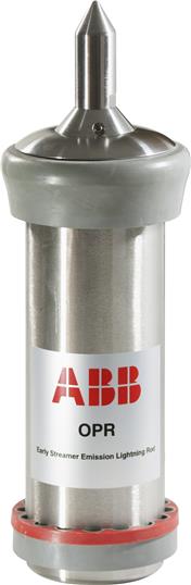
OPR, the high pulse voltage, initiation advance lightning
air terminal 26
Early Streamer Emission Air Terminal - ESEAT 27
Single Rod Air Terminal - SRAT 29
Extension masts 30
Masts and extension masts 31
Pylons 32
Lateral fixations 33
Roof fixing accessories 35
Conductors and coupling accessories 36
Conductor fasteners 37
Earth coupling accessories 39
Earthing system 40
Equipotential bonding 43
Meshed conductors
Typical installation 44
Accessories 45
Index 46
OPR lightning protection systems
External lightning protection
1TXH000247C0203 - Edition June 2016
2 | ABB OPR lightning protection systems
Lightning mechanism and location
Storms
The presence of unstable, moist and warm air masses gives
rise to the formation of cumulonimbus storm clouds. This type
of cloud is very extensive, both horizontally (about 10 km in
diameter) and vertically (up to 15 km). Its highly characteristic
shape is often compared with the profile of an anvil of which
it displays the upper and lower horizontal planes. The existence
of extreme temperature gradients in a cumulonimbus
(the temperature can drop to -65 °C at the top) generates
very rapid ascending air currents, and results in the electrical
energisation of the water particles.
In a typical storm cloud, the upper part, consisting of ice
crystals, is normally positively charged, whilst the lower part,
consisting of water droplets, is negatively charged. Consequently,
the lower part of the cloud causes the development
of electrically opposite charges (i.e. positive over the part of
the ground nearby).
Thus the cumulonimbus formation constitutes a sort of huge
plate /ground capacitor whose median distance can often
reach 1 to 2 km. The atmospheric electrical field on the
ground, about 600 V/m in fine weather is reversed and can
reach an absolute value of 15 to 20 kV/m when a ground
discharge is imminent (the lightning stroke).
Before and during the appearance of the lightning stroke,
discharges can be seen both within the cloud and between
clouds.
Lightning
According to the direction in which the electrical discharge
develops (downward or upward), and the polarity of the
charges it develops (negative or positive), four classes of
cloud-to-ground lightning stroke can be distinguished. In
practice, lightning strokes of the descending and negative
type are by far the most frequent: it is estimated that on plains
and in our temperate zones, they account for 96 % of all
cloud / ground discharges.
Mechanism of a lightning stroke
It is impossible to discern the individual phases of the lightning
stroke by simple visual observation. This can only be
done with high-speed cameras. Most lightning bolts exhibit
the following phenomena: a leader leaves a point in the
cloud and travels about 50 m at a very high speed of around
50 000 km/s. A second leader then leaves the same point,
follows the previous path at comparable speed, goes beyond
the final point of the first leader by an approximately identical
distance, then disappears in turn.
The process is repeated until the tip of the last leader reaches
a point a few dozen metres, or even just a few metres above
ground level.
The ascending jets then converge, producing a return stroke
from the ground towards the cloud (the upward streamer) during
which the electric current circulates: The convergence of
these two phenomena produces the main discharge, which
may be followed by a series of secondary discharges, passing
unbroken along the channel ionised by the main discharge.
In an average negative lightning stroke, the maximum current
is around 35 000 A.
-
-
-
-
-
-
-
-
-
-
- - - -
+
+
+ +
+
+
+ + +
+
+
+
+
+
+
+
+
+ + + + + + + + + + + + + + + + + + + +
ABB OPR lightning protection systems | 3
Lightning protection technologies
The effects of lightning
The effects of lightning are those of a high-strength impulse
current that propagates initially in a gaseous environment (the
atmosphere), and then in a solid, more or less conductive
medium (the ground):
– visual effects (flash): caused by the Townsend avalanche
mechanism
– acoustic effects: caused by the propagation of a shock
wave (rise in pressure) originating in the discharge path;
this effect is perceptible up to a range of around 10 km
– thermal effect: heat generated by the Joule effect in the
ionised channel
– electrodynamic effects: these are the mechanical forces applied
to the conductors placed in a magnetic field created
by the high voltage circulation. They may result in deformations
– electrochemical effects: these relatively minor effects are
conveyed in the form of electrolytic decomposition through
the application of Faraday's law
– induction effects: in a variable electroma-gnetic field, every
conductor harnesses induced current
– effects on a living being (human or animal): the passage of
a transient current of a certain r.m.s value is sufficient to
incur risks of electrocution by heart attack or respiratory
failure, together with the risk of burns.
Lightning causes two major types of accidents:
– accidents caused by a direct stroke when the lightning
strikes a building or a specific zone. This can cause considerable
damage, usually by fire. Protection against this
danger is provided by lightning air terminal systems
– accidents caused indirectly, as when the lightning strikes or
causes power surges in power cables or transmission links.
Hence the need to protect with SPD the equipment at risk
against the surge voltage and indirect currents generated.
Protection against direct lightning stroke
To protect a structure against lightning strokes, a preferred
impact point is selected to protect the surrounding structure
and conduct the flow of the electric current towards the
ground, with minimal impedance on the path followed by
the lightning. Four types of protection systems meet these
requirements.
Protection systems Standards
Early streamer emission air terminal - France: NF C 17-102 (September 2011 edition)
- Argentina: IRAM 2426
- Spain: UNE 21186
- Macedonia: MKS N.B4 810
- Portugal: NP 4426
- Romania: I-20
- Slovakia: STN 34 1391
- Serbia: JUS N.B4.810
Single rods air terminals IEC 62 305-3
Meshed cages IEC 62 305-3
Stretched wires IEC 62 305-3
4 | ABB OPR lightning protection systems
Lightning protection system with early streamer emission
air terminal (ESEAT)
These state-of-the-art technologies have been designed on
the basis of a series of patents registered jointly by HELITA
and the French National Scientific Research Centre (CNRS).
The OPR is equipped with an electronic device which is high
pulse voltage of known and controlled frequency and amplitude
enabling the early formation of the upward leader which is
then continuously propagated towards the downward leader.
This anticipation in the upward leader formation is essential
with regard to the last scientific knowledge on the lightning
attachment that acknowledge the fact that this one results
from an upward leader competition. Today the upward leader
competition is internationally recognized thanks to high speed
cameras pictures of this phenomenon of attachment and to its
digital simulation.
The OPR draws its energy from the ambient electrical field
during the storm. After capturing the lightning stroke, the OPR
directs it towards the down conductors to the ground where it
is dissipated.
Triggering time of an ESEAT
1 2
Lightning protection technologies
ABB OPR lightning protection systems | 5
The early streamer emission (ESE) concept
During a storm, when the propagation field conditions are
favourable, the OPR first generates an upward leader. This
leader from the OPR tip propagates towards the downward
leader from the cloud at an average speed of 1 m/µs.
The triggering time ∆T (µs) is defined as the mean gain at
the sparkover instant (continuous propagation of the upward
leader) obtained with an ESE air terminal compared with a
single rod air terminal exposed to the same conditions. ∆T is
measured in the high-voltage laboratory, all tests are defined
in appendix C of the French standard NF C 17-102.
The triggering time instance gain ∆T is associated with a
triggering time distance gain ∆L.
∆L = v. ∆T, where:
– ∆L (m): gain in lead distance or sparkover distance
– v (m/µs): average speed of the downward tracer (1 m/µs).
– ∆T (µs): gain in sparkover time of the upward leader
measured in laboratory conditions.
OPR air terminals are especially effective for the protection
of classified industrial sites, administrative or public buildings,
historical monuments and open-air sites such as sports
grounds.
Lightning protection technologies
6 | ABB OPR lightning protection systems
Lightning protection technologies
Lightning protection system with meshed cages
This principle consists of dividing up and more easily dissipating the
lightning current by a network of conductors and earths.
A meshed cage installation has multiple down conductors and
consequently provides very effective protection for buildings
that house equipment sensitive to electromagnetic disturbance.
This is because the lightning current is divided among the down
conductors and the low current circulating in the mesh creates very
little disturbance by induction.
A meshed cage installation is made up of:
– devices to capture the atmospheric discharges consisting of
strike points
– roof conductors
– down conductors
– protection measures against injuries to leaving being due to
touch and step voltages (e.g. warning notice)
– an equipotential bonding between each earth and the general
earthing circuit of the structure; this one must be disconnectable.
Installation conditions
Lightning Protection System with an ESEAT is made of:
– an Early Streamer Emission Air Terminal and its extension mast
– two down conductors, or in case of several ESEAT one
conductor per ESEAT
– a connecting link or test joint for each down conductor to
enabling the earth resistance to be verified
– a protecting flat to protect the down conductor for the last two
meters above ground level
– an earth designed to dissipate the lightning currents at the
bottom of each down conductor
– an equipotential bonding between each earth and the general
earthing circuit of the structure; this one must be disconnectable
– protection measures against injuries to leaving being due to
touch and step voltages (e.g. warning notice).
Lightning protection system with single rod air terminal
By protruding upwards from the building, they are likely to trigger
the release of ascending streamers and thus be selected as
impact points by lightning strokes occurring within the vicinity of the
structure.
This type of protection is especially recommended for radio stations
and antenna masts when the area requiring protection is relatively
small.
A single rod air terminal protection is made up of:
– a rod lightning air terminal and its extension mast
– two down conductors
– a connection link or test joint on each down conductor to check
the conductor earth resistance
– a protecting flat to protect the down conductor for the last two
meters above ground level
– an equipotential bonding between each earth and the general
earthing circuit of the structure; this one must be disconnectable
– protection measures against injuries to leaving being due to
touch and step voltages (eg warning notice).
ABB OPR lightning protection systems | 7
Lightning protection technologies
Stretched wires
This system is composed of one or several conductor wires
stretched above the protected installation. The protection area is
determined by applying the electro-geometrical model.
The conductors must be earthed at each end.
A stretched wire installation requires a thorough preliminary study
to consider issues such as mechanical strength, the type of
installation, and the insulation distances.
This technology is used to protect ammunition depots and as a
general rule in circumstances where the site cannot be protected
by using a building structure to support the conductors that
convey the lightning currents to the earth.
Protection against indirect lightning stroke effects
When lightning strikes cables and transmission lines (H.F. coaxial
cables, telecommunication lines, power cables), a voltage surge
is propagated and may reach equipment in the surrounding. This
voltage surge can also be generated by induction due to the
electromagnetic radiation of the lightning flash.
This can have many consequences: premature component
ageing, destruction of printed circuit boards or component plating,
equipment failure, data loss, programs hanging, line damage,
etc. This is why you need to use Surge Protective Devices to
protect equipment liable to be affected by lightning strikes.
The use of Surge Protective Devices is highly recommended
when the building is fitted with an external lightning protection. A
type 1 SPD is highly recommended or even mandatory in some
countries. A good protection is made in step with one type 1 fitted
in the MDB when the SDB are fitted with type 2 SPDs.
Early Streamer Emission
Air Terminal
MDB
SDB - Sub
Distribution Board
SDB
Telephone input
Main
power input
MDB - Main
Distribution Board
Telecom
board
Equipotential bonding of metal parts
During a lightning stroke or even as a result of indirect effects,
equipotential bonding defects can, by differences in potential,
generate sparkover causing risk for human being or fire into the
structure.
This is why it is an essential part of effective lightning protection to
ensure that a site's equipotential bonding is effective and in good
condition.
The necessity of an electrical insulation between the air termination
or the down-conductor and the structural metal parts, the
metal installations and the internal systems can be achieved by
providing a separation distance "s" between the parts.
8 | ABB OPR lightning protection systems
Lightning protection risk analysis
Risk analysis
All lightning protection standards recommend a preliminary
lightning risk analysis in three parts:
– lightning risk evaluation
– protection level selection
– protection device definition.
We have developed a software based on the calculations of
the IEC 62305-2 or NF C 17-102 (appendix A) in order to give
you an easy and accurate solution regarding the risk analysis
of any installation you wish to protect.
Lightning flash density map (flashes per km² per year)
Protection device definition
It is advisable to take into account the technical and architectural
constraints when configuring the different components of
the protection device.
To facilitate your preliminary studies, we will provide a questionnaire
in which the minimum required information can be
entered, and a calculation software package.
2 < Ng < 8
8 < Ng < 18
ABB OPR lightning protection systems | 9
Lightning protection technical study
OPR Designer software
ABB is happy to provide you with a complete new software in the field of lightning
protection.
With a very simple approach you can create your technical study in one click!
You can either draw, import file (AutoCAD, pictures…)
and from that point get a complete bill of material
(air terminals, down conductors, fixing accessories
and earthing system), the positioning of the lightning
protection system on the structure.
The solution is given in a complete pdf file that includes :
– protected areas
– lightning air terminals positioning
– complete bill of material
– detailed bill of material per building
– catalogue pages for each component
– test certificates
This software is so far available in English, French, Spanish,
Russian and Lithuanian version.
You may download OPR designer at the following address :
http://www.web-emedia.com/opr/
10 | ABB OPR lightning protection systems
Procedure for measuring the Early Streamer Emission of an ESE
air terminal according to standard NF C 17-102 appendix C
This test procedure consists in evaluating the triggering time
of an Early Streamer Emission (ESEAT) compared with the
reference Single Rod Air Terminal (SRAT) in high voltage laboratory
conditions. 50 shocks are applied to the single rod air terminal
in the first configuration, then to the early streamer emission air
terminal in a second configuration.
Simulation of natural conditions
Natural conditions can be simulated in a laboratory by superimposing
a permanent field and an impulse field associated with a plate /
ground platform area (H). The tested lightning air terminal is placed
on the ground, beneath the centre of this platform. In the experiment,
the height H = 6 m, and the lightning air terminal height
h = 1.5 m.
Electrical conditions
The permanent field caused by the charge distribution in the
cloud is represented by a negative DC voltage of -20 to -25 kV/m
(simulating a negative field of around -20 to -25 kV/m) applied to
the upper plate. The impulse field caused by the approach of the
download leader is simulated with a negative polarity wave applied
to the platform. The rise time of the wave Tm is 650 µs. The wave
gradient, at the significant points is around 109
V/m/s.
Geometrical conditions
The volume used for the experiment must be large enough to allow
the ascending discharge to develop freely:
– distance d between upper platform and tip ≥ 1 m
– upper plate diameter ≥ distance from upper plate to ground.
The lightning air terminal are tested in sequence in strictly identical
geometrical conditions same height, same location, same distance
between tip and upper platform.
ESE air terminals triggering time calculation
General conditions
– number of shocks: around 50 per configuration (sufficient for an
accurate analysis of the leader /Leader transition)
– interval between shocks: the same for each configuration equal
to 2 min.
Recording
– triggering time (TB): obtained directly by reading the data from
the diagnostic equipment. This data is not characteristic, but
it does enable a simple reading to establish whether or not a
shock can yield a valid result
– light emitted by the leader at the lightning air terminal tip (photomultipliers):
this data provides a very accurate detection of the
leader continuous propagation instant
– pre-discharge current (coaxial shunt): the resulting curves confirm
the previous diagnostic data
– space-time development of the discharge (image converter): the
image converter pictures provide a further means of analysing
the results.
SRAT
LABORATORY EARTH
d
h
H
PLATE
d
h
H
ESEAT
LABORATORY EARTH
PLATE
IREQ Laboratory (Canada - 2000)
Other recordings and measurements
– short-circuit current (coaxial shunt)
– time/voltage characteristics for several shocks
– rod to plate distance before and after each configuration
– climatic parameters must be maintain for the 2 configurations :
- pressure ±2 %
- temperature ±10 %
- relative humidity ±20 %.
Triggering picture of a SRAT with
a rotative high speed camera.
Triggering picture of an ESEAT with
a rotative high speed camera.
ABB OPR lightning protection systems | 11
Procedure for measuring the Early Streamer Emission of an ESE
air terminal according to standard NF C 17-102 appendix C
Procedure for measuring the Early Streamer Emission of an ESE
air terminal according to standard NF C 17-102 appendix C
T TESEATTSRAT t(µs)
EESEAT
ESRAT
EM exp
reference wave
measuring wave
Determination of the early streamer emission of the ESEAT
The triggering time instants, or continuous propagation
instants of the upward leader are obtained by analysing the
diagnostic data described above. The mean is then calculated
for each lightning air terminal tested, and the difference
between the mean values is the ESE lightning air terminal
triggering time.
T= TSRAT - TESEAT
ABB lightning protection group has unique know-how and
experience in this field.
Since 1996, we have generated more than 40 000 sparks
using this test procedure in the following high voltage
laboratories:
– SIAME Laboratory - PAU UNIVERSITY (France)
– Bazet VHV Laboratory - SEDIVER (France)
– Volta HV Laboratory - MERLIN GERIN (France)
– L.G.E.Les Renardières - ELECTRICITE DE FRANCE
– Bagnères de Bigorre HV Laboratory - LEHTM (France)
– Varennes IREQ Laboratory (Canada)
– Korea Electrotechnology Research Institute - KERI (Korea)
– WHVRI - Wuhan High Voltage Research Institute (China)
– Beijing testing center surge protective devices (China).
12 | ABB OPR lightning protection systems
Tests and research
Objectives
ABB Lightning Protection Group has been investing for many
years in research into lightning air terminal protection devices,
and is constantly striving to enhance the performance of its
products.
ABB's ongoing in situ research in France and abroad has three
main objectives:
– to enhance the protection models
– to measure in situ the effectiveness of ESEAT, already
evaluated in laboratory conditions
– to qualify the dimensioning of the equipment in real-life
lightning strike conditions.
Tests under Laboratory conditions
Since 2003 our factory located in Bagnères de Bigorre
(France) has a high tech laboratory allowing to test our Surge
Protective Devices in 10/350 µs and 8/20 µs wave shapes as
well as our direct lightning range with lightning currents up to
100 kA.
We also test our lighting rods in a dedicated high voltage
laboratory close to our factory allowing normative tests thanks
to an up to 3 MV generator.
Tests in situs
An experimental site devoted to the study of direct lightning
impacts to a lightning protection system has been selected at
the top of the "Pic du Midi" in the French Pyrenées mountains
for its high lightning impact density (30 days of storm per
year).
The "Pic du Midi", famous astronomical observatory, offers
an unique scientific environment for lightning observations in
collaboration with astronomers.
Purpose of the experiments:
– to confirm the triggering time of ESEAT compared to single
rod air terminals
– to direct the flow of the lightning currents captured by the
lightning air terminal to low-voltage surge arresters via an
appropriate earthing network
– to test the resistance of the equipment to lightning shocks
and climatological constraints.
ABB OPR lightning protection systems | 13
In situ tests at the Pic du Midi de Bigorre
This unique location enables us to test our products in highly
severe conditions (high winds, extremely low temperatures) as
these tests are running at an altitude of 2880 m.
Such tests give us the opportunity to complete our
understanding on lightning phenomenon. For this purpose, we
are using high speed cameras, lightning current recorders as
well as field and light recorders.
Another in situ test runs at the Taoulet station 2300 m to verify
that theoretical values announced are also validated in real
conditions.
A constant partnership with scientists permits to follow these
in situs sites and lead to fundamental research on lighting. As
an application example, a software that determines the weak
points of a structure has been developed.
Natural lightning experimental site
– Located in the Hautes Pyrénées department of France
– Keraunic level: 30 days of storms per annum.
Experimental artificial lightning triggering sites
Because lightning is a randomly occurring natural
phenomenon, artificial triggering techniques have been
developed to speed up the research process.
When lightning conditions are prevalent the triggering
technique consists in sending a rocket with a trailing wire in
the direction of the storm clouds to cause a lightning strike at
the experimental site.
The wire may comprise an insulating section in order to
generate the largest possible number of lightning strikes for
experimental purposes.
– Site located at Privat d'Allier in Auvergne, France
Keraunic level: 30
Purpose of the experiments:
- to qualify the lightning strike counters and
- low-voltage arresters in situ
- to qualify the resistance of the equipment to
- triggered lightning strikes.
– Site located at Camp Blanding (Florida/USA)
Keraunic level: 80
Purpose of the experiments:
- to confirm the triggering time gain of the ESE air terminals
compared with single rod air terminals
- to collect data with a view to improving the protection
models.
Tests and research
14 | ABB OPR lightning protection systems
Lightning capture devices
Lightning air terminals
Early Streamer Emission Air Terminals (ESEAT) or Single
Rod Air Terminals (SRAT).
As a general rule, the lightning air terminal should culminate at
least two metres above the highest points of the building(s) to
be protected.
Its location should therefore be determined relative to building
superstructures: chimneys, machine and equipment rooms,
flagpoles, pylons or aerials. Ideally, these vulnerable points
should be selected for lightning air terminal installation.
The lightning air terminal may be raised by an extension mast.
Our stainless steel interlocking extension masts can reach
an overall height of 8.50 or 11 m including the lightning air
terminal height. They have been specially designed to obviate
the need for guying. However, if guying is essential (e.g. when
the conductor is fixed with a flat support on the roof waterproofing,
or is exposed to particularly strong winds), the guys
should be made of Ø 5.6 fibre glass. When metal cables are
used for guying, the lower anchoring points should be interconnected
with the down conductor by a conductive material
of the same type. We offer a range of fixtures adapted to most
requirements.
Installation specifications are detailed in the individual product
data sheets.
If several lightning air terminals (ESEAT or SRAT) are used in
the outside installation on the same structure, they should be
connected by a conductor, except when this has to pass an
obstacle of more than 40 cm in height.
D ≤ 40 cm: connect ESEATs
D ≥ 40 cm: do not connect air terminals
When protecting open-air sites such as sports grounds, golf
courses, swimming pools, and camping sites, ESEATs are
installed on special supports such as lighting masts, pylons,
or any other nearby structures from which the conductor can
cover the area to be protected.
Our software OPR Designer is able to design a complete
lightning protection system with all installations details, listing
of material, protections areas layout, tests certificates within a
complete technical document that is available for the client in
pdf format.
d ≤ 40 cm d ≤ 40 cm d ≤ 40 cm
Interconnection rule when several ESEAT on the same roof
ABB OPR lightning protection systems | 15
Lightning capture devices
Special cases
Antennas
By agreement with the user of the antenna, the device can
be mounted on the antenna mast, provided that allowance is
made for a number of factors notably:
– the lightning air terminal tip must culminate at least 2 m
above the antenna
– the aerial coaxial cable is routed inside the antenna mast
– the common supporting mast will no need guying
– the connection to the down conductor will be made using a
clamp fixed to the foot of the mast.
This process, widely used today, offers three advantages:
– technical (it earths the aerial itself)
– visual (there is only one mast)
– cost.
To be noted that an ESEAT electronic generator cannot be
used in an atmosphere where the temperature is greater than
120°.
Industrial chimney
ESE air terminal:
– the lightning air terminal should be mounted on an offset
mast (2CTH0HRI3501) as far as possible from smoke and
corrosive vapours
– the mast should be fixed to 2 points as shown in the diagram.
To be noted that an ESEAT electronic generator cannot be
used in an atmosphere where the temperature is greater than
120°.
Single rod air terminal:
The lightning air terminals (1 or 2 m) should be mounted on
stainless steel supports (2CTH0HPS2630) to enable mounting
at a 30° angle. They will be interconnected by a belt conductor
positioned 50 cm from the summit of the chimney.
When using 1 m air terminal at least two points should be
used and placed at intervals of no more than 2 m around the
perimeter.
When using strike points of at least 2 m in height, the number
of points should be calculated to cover the protection radius.
Steeple
The lightning air terminal have been designed to carry roof
ornaments (rooster, weathervane, cardinal points, etc.).
The down conductor is then fixed below the ornaments.
2 m
minimum
ESEAT
Ø 35 mm stainless steel
ESEAT mast
2CTH070011R0000
500 mm
antenna
steel hoops
down
conductor
ESEAT
offset mast
down conductor
wind indicator
rooster
tightening screw
cardinal
points
connecting clamp
750 mm
ESEAT base
down conductor
ESEAT
16 | ABB OPR lightning protection systems
Down conductors
Overview
Down conductors should preferably be made with tin-plated
red copper strips, 30 mm wide and 2 mm thick.
Lightning is a high frequency current that flows along the
periphery of the conductors. For a like cross-section, a flat
conductor has a greater periphery.
An exception to the above rule is buildings with aluminium
cladding on which a copper down conductor might generate
an electrolytic coupling phenomenon.
Here a 30 x 3 mm aluminium strip should be used or bimetal
connection.
In some cases where it is impossible to fix the copper strip, a
round Ø 8 mm tin-plated copper conductor. In the case where
there is a need of mechanical movement of the down conductor
use a 30 x 3 mm flexible tin-platted copper braid.
Path
The path should be planned to take account of the location of
the earth termination. The path should be as straight and short
as possible avoiding any sharp bends or upturns. Curvature
radii should be no less than 20 cm. To divert the down conductor
laterally, 30 x 2 mm tin-plated red copper preformed
bends should be used.
The down conductor path should be chosen to avoid intersection
and to be routed along electrical ducts. Shielding
the electrical ducts 1 m on each side can be done when it is
impossible to avoid crossing them. However when crossovers
cannot be avoided, the conduit should be protected inside
metal sheeting extending by 1 m on either side of the crossover.
This metal sheeting should be connected to the down
conductor.
However, in exceptional cases where an outside down
conductor cannot be installed, the conductor may run down
through a service duct, provided that this is used for no other
purpose (and subject to agreement with the safety services
and inspection organizations).
When a building is fitted with a metallic external cladding or
stone facing or in glass, or in the case of a fixed covering part
of the facade, the down conductor can be installed on the
concrete facade or on the main structure, under the cladding.
In this case, the conductive parts of the cladding must be
connected to the down conductor at the top and at the
bottom.
The down conductor, if not a copper one, shall be located at
more than 10 cm behind inflammable material of the outside
cladding if its cross section area if lower than 100 mm². For
cross section area of 100 mm² or greater, there is no need to
keep a distance between the down conductor and the
flammable material.
A specific calculation of the temperature increase may be performed
to validate a different rule.
The same requirements apply also to all inflammable material
even on the roof (e.g. thatched roof).
Indoor routing
When a down conductor cannot be installed outside the
structure, it can be fitted inside on a part or on the full height
of the structure. In this case, the down conductor must be
placed inside a dedicated non flammable and insulating duct.
The separation distance shall be calculated also for indoor
down conductors in order to be able to determine the necessary
insulation level of the dedicated duct.
The building operator has to be aware of the resulting
difficulties to check and maintain the down conductors, and of
the resulting risks of over voltages inside the building.
Access of people to the specific cable channel should be
avoided in stormy periods or measures of protection as per
outdoor down conductors should be fulfilled (see Annex D
NF C 17-102 Vers September 2011) including equipotential
bondings of floors with the down conductor.
Down-conductor bend shapes
L
d L
d
L
d
L
L
d
d
L: length of the loop,
in meters
d: width of the loop,
in meters
The risk of any dielectric
breakdown is avoided if
the condition d>L/20
is fulfilled.
ABB OPR lightning protection systems | 17
Down conductors
Parapet walls
When the face of the parapet wall is less than or equal to
40 cm, an upward section in the down conductor is allowed
with a maximum slope of no more than 45°. For parapet walls
with an upward section of more than 40 cm, space should be
allowed or a hole drilled to accommodate a 50 mm minimum
diameter sheath and thereby avoid bypassing. If this is not
possible, supports of the same height as the parapet wall
should be installed to avoid an upturn.
Connection
The lightning air terminal is connected to the down
conductor by a connecting clamp that must be tightly secured
on to the mast. The strip will be secured along the extension
masts by stainless steel clamps. The conductors can be
connected together by coupling strips.
Fasteners
Whatever the supporting medium the down conductor must
be secured by at least 3 fasteners per linear meter. Insulators
are used to distance the conductors and prevent contact with
easily flammable material (thatch or wood, for example).
The fastener must be appropriate for the structure material
and installed so as not to impair watertightness and allow the
conductor thermal extension.
Test joint
Each down conductor must be fitted with a test joint or connection
link to enable measurement of the resistance of the
lightning earth system alone and the electrical continuity of the
down conductor.
The test coupling is usually placed about 2 m above ground
level to make it accessible for inspection purposes only. To be
compliant with standards, the test joint should be identified by
the words "lightning air terminal" and the "earth" symbol.
On metal pylons, framework or cladding, the test joint should
be placed on the ground in inspection earth pit about 1 m from
the foot of the metal wall to avoid distorting the resistance
measurement of the earth connection by inevitably measuring
the electrical resistance on the other metallic networks in the
building.
Protecting flat
Between the test joint and the ground, the strip is protected
by a 2 m galvanized or stainless steel sheet metal flat fixed by
3 clamps supplied with the flat.
The protecting flat can be bent to follow the profile of the
building.
Warning Notice: Protection measures against step and
touch voltages
In certain conditions, the vicinity of the down-conductors of an
ESE System, outside the structure, may be hazardous to life
strip 30 x 2 mm
copper round
ø 6 or 8 mm
330
lead play
30 or 40
30
test joint
protecting
at
hook
down conductor
strip
lead dowel
copper tape
30 x 2 mm
3 screw-in stainless
steel clamps on the
2 m of protecting at
protecting at
even if the ESE System has been designed and constructed
according to the above-mentioned requirements.
The hazard is reduced to a tolerable level if one of the
following conditions is fulfilled:
The probability of persons approaching, or the duration of
their presence outside the structure and close to the downconductors,
is very low. The natural down-conductor system
consists of typically more than ten columns of the extensive
metal framework of the structure or of several pillars of
interconnected steel of the structure, with the electrical
continuity assured;
The contact resistance of the surface layer of the soil, within
3 m of the down-conductor, is not less than 100 kΩ.
NOTE: A layer of insulating material, e.g. asphalt, of 5 cm
thickness (or a layer of gravel 15 cm thick) generally reduces
the hazard to a tolerable level. If none of these conditions is
fulfilled, protection measures shall be adopted against injury to
living beings due to touch voltages as follows:
– insulation of the exposed down-conductor is provided
giving a 100 kV, 1.2/50 μs impulse withstand voltage,
e.g. at least 3 mm cross-linked polyethylene
– physical restrictions and/or warning notices to minimize the
probability of down-conductors being touched. We propose
in our catalogue Warning Notice (2CTH0PSH2009) to
prevent touch voltage.
40 cm
max
45°
max
Warning Notice
18 | ABB OPR lightning protection systems
Down conductors
Lightning stroke counter
When the regulations require the installation of a lightning
stroke counter, or to know when to make a complete verification
of the installation after a lightning stroke. One per ESEAT
or SRAT should be fitted. Regarding mesh cage installation
one every 4 down conductor should be installed. The test joint
around 2 m above the ground. The counter is connected in
serial on the down conductor.
Lightning stroke counter and recorder is used to store date
and time of the impact as well as lightning current values.
Meshed conductors
On roof
Is carried on the roof meshes with conductors of which the
width depends on the level of protection and those ones must
not be greater than 20 m as follows:
It is primarily a closed polygon whose perimeter is adjacent
the periphery of the roof, this polygon is then complete by
transverse conductors to satisfy the condition on the maximum
width of the meshes. If there is a ridge, the conductor
must follow it.
Air terminals are placed vertically at the highest and most
vulnerable points on the buildings (roof ridges, salient points,
edges, corners, etc.).
They are arranged at regular intervals around the periphery of
the roof as follows:
– the distance between two 30 cm air terminals should not
exceed 15 m
– the distance between two 50 cm air terminals should not
exceed 20 m
– strike air terminals not located on the outer polygon are
connected to the polygon as follows:
- either by a conductor excluding any upturn if the air terminals
is less than 5 m from the polygon
- or by two conductors in opposite directions forming a
transversal section if the air terminals is located more
than 5 m from the polygon.
On wall
The down conductors are placed on the corners and salient
features of the building in a layout that should be as symmetrical
and regular as possible.
The average distance between two adjacent down conductors
depends on the required protection level.
Protection level
(IEC 62305-2)
Distance between 2 down
conductors (IEC 62305-3)
Roof mesh size
(IEC 62305-3)
I 10 m 5 x 5
II 10 m 10 x 10
III 15 m 15 x 15
IV 20 m 20 x 20
ABB OPR lightning protection systems | 19
Equipotential bonding
Overview
When lightning current flows through a conductor, differences
in potential appear between the conductor and nearby metallic
networks (steel framework, pipes, etc.) inside or outside
the building. Dangerous sparks may be produced between
the two ends of the resulting open loop.
There are two ways to avoid this problem:
a) Establish an interconnection providing an equipotential
bond between the conductor and the metallic networks
b) Allow a separation distance between the conductor and the
metallic networks.
The separation distance is the distance beyond which no dangerous
sparks can be produced between the down conductor
carrying the lightning current and nearby metallic networks.
Because it is often difficult to guarantee that the lightning
protection system is sufficiently isolated during installation or
will remain so in the event of structural changes, on-site work,
etc., equipotential bonding is often preferred.
There are, however, some cases in which equipotential bonding
is not used (e.g. when there are flammable or explosive
piping net-works). In this case, the down conductors are
routed beyond the separation distance "s".
Separation distance calculation
S (m) = ki.kc.L
km
where:
"kc" is a coefficient determined by the number of down
conductors per ESEAT:
kc = 1 for one down conductor, kc = 0.75 for two down conductors,
kc = 0.6 for three conductors, kc = 0.41 for four or
more conductors.
" ki " is determined by the required protection level:
ki = 0.08 for protection level 1 (high protection), for very
exposed or strategic buildings
ki = 0.06 for protection level 2 (reinforced protection, exposed
building)
ki = 0.04 for protection level 3 & 4 (standard protection)
"km" is related to the material situated between the two
loop ends:
km : 1 for air
km = 0.5 for a solid material other than metal
"L" is the length between the point at which proximity is
measured and the point at which the metallic network is
earthed or the nearest equipotential bonding point.
S1
L1
L2
S2
air conditioning
earthing
bar
Example
An ESEAT with two down conductors protects a 20 m high
building with protection level I.
– Question 1 : Should an air conditioning extractor located
on the roof be interconnected if 3 m away from the down
conductor? Length L1 = 25 m.
Answer 1 : S1 = 0.08 x 0.75 x 25 / 1 = 1.5 m
Since the distance (3 m) between the conductor and the airconditioning
system is greater than the separation distance
(1.5 meters), there is no need to interconnect this extractor.
– Question 2 : Should the computer located in the building 3
m away from the down conductor be interconnected with
the conductor, where L2 = 10 m?
Answer 2 : S2 = 0.08 x 0.75 x 10 / 0.5 = 1.2 m
Since the distance between the computer and the down
conductor (3 m) is greater than the separation distance
(1.2 m), there is no need to interconnect this computer.
A tool is available that can be used to quickly calculate the
separation distances.
20 | ABB OPR lightning protection systems
Equipotential bonding
Equipotential bonding of external metallic networks
The equipotential bonding of external metallic networks is an
integral part of the outdoor lightning protection installation just
like the down conductors and their earths.
All conductive metallic networks located at a distance of less
than s (separation distance) from a conductor should be
connected to the conductor by a conductive material with a
like cross-section.
The aerial masts and small posts supporting electrical power
lines should be connected to the conductor via a mast
arrester. Earthing systems embedded in walls should be
connected to the conductor if terminal connections have been
provided.
Equipotential bonding of internal metallic networks
The equipotential bonding of internal metallic networks is an
integral part of the indoor lightning protection installation.
All conductive metallic networks in the structure (steel
frameworks, ducts, sheathing, electrical raceways or telecommunication
cable trays, etc.) should be connected to the
conductor. This is done by using a conductive material with
a cross-section of at least 6 mm² for copper or 16 mm² for
steel to connect to equipotential bonding bars installed inside
the structure and connected in turn to the closest point of the
earthing circuit.
Unscreened telecommunication or electrical conductors
should be bonded to the lightning protection system via surge
arresters.
Equipotential bonding of earths
This is done by using a conductive material with a
cross-section of at least 16 mm² for copper or 50 mm²
for steel to connect bonding bar to earth termination system.
interconnection with
building loop
1
1
2
2
3
3
telephone line protection
low voltage power supply
protection
IT system protection
4
4
TV protection
ESEAT OPR
ABB OPR lightning protection systems | 21
Earth termination systems
Overview
Each down conductor in a lightning protection system must be
connected to an earth termination system which fulfils four conditions:
– The earth termination resistance value
International standards stipulate an earth termination resistance
value of less than 10 ohms.
This value should be measured on the earth connection isolated
from any other conductive component.
If the resistance value of 10 ohms cannot be achieved, the earth
termination is nonetheless considered compliant if it is made up of
at least 160 m (protection level 1) or 100 m (protection level 2, 3
& 4) of conductors or electrodes, each section measuring no more
than 20 m.
– Current carrying capacity
This is an often overlooked but essential aspect of lightning
conduction. To minimise the earthing system impedance value,
a parallel configuration of three electrodes is strongly recommended
instead of just one excessively long electrode.
– Equipotential bonding
Standards require the equipotential bonding of lightning
earth termination systems with the existing earthing systems.
This must be done using 16 mm² (copper) or 50 mm² (steel)
minimum cross section conductor.
– Distance from buried utilities
Earth termination should be at least 2 m (if soil resistivity is over
500 ohms/m 5 m) distant from any buried metal pipe or electrical
conduit, not connected to the main equipotential bonding of the
structure.
Inspection earth pit
The connection parts of an earth termination system (duck's foot
connector, earth rod, test joint) can be accessed in an inspection earth
pit.
Lightning air terminals
Ducks foot connector
The minimum earth termination system is made up of 25 m of
30 x 2 mm tin-plated copper strip, split into 3 strands buried in
3 trenches at a depth of 60 to 80 cm dug in a fan shape like a duck's
foot: one end of the longest strand is connected to the test joint, the
two other strands being linked to a special connection known as a
duck foot's connector.
Earth rods
When the site topography does not lend itself to the installation of a
duck's foot as described above, an earth termination system can be
developed using at least 3 copper earth rods each with a minimum
length of 2 m, buried vertically in the ground; the rods should be
spaced at intervals of about 2 m and at a mandatory distance of 1 m
to 1.5 m from the foundations.
protection
at
30 x 2 mm down conductor
6 to 9 m depending
on soil
resistance
1 m from wall depth
60 to 80 cm
8 to 12 m
stainless
steel clamp
NB: the earth termination is covered
by a red or orange warning grid
DUCK'S FOOT EARTH
TERMINATION SYSTEM
duck's
foot
connector
Duck's foot earth termination system
It is recommended to cover the earth termination system with a red or orange warning
plastic mesh.
protection
at
30 x 2 mm strip
2 m
1 m from wall depth
60 to 80 cm
stainless steel
clamp
NB: the earth termination
is covered by a red
or orange warning grid 2 m rodearth rod clamp
ROD TRIANGLE EARTH
TERMINATION SYSTEM
Rod triangle earth termination system
It is recommended to cover the earth termination system with a red or orange warning
plastic mesh.
DUCK'S FOOT EARTH TERMINATION
SYSTEM WITH EARTH RODS
protection
at
30 x 2 mm strip
8 to 12 m
depth 6 to 9 m 60 to 80 cm
duck's
foot
connector
stainless
steel clamp
NB: the earth termination
is covered by a red or
orange warning grid
rodearth rod
clamp
1 m from wall
Duck's foot earth termination system with earth rods
It is recommended to cover the earth termination system with a red or orange warning
plastic mesh.
22 | ABB OPR lightning protection systems
Earth termination systems
Combined
If the soil type is not altogether suitable for a duck's foot connector,
a combination of duck's foot and earth rods will significantly
enhance protection (better earth resistance). In this case, the end
of each duck foot connector strand is connected to an earth rod.
Meshed conductors
Duck's foot connector
The earth connection is made up of 3 conductors each 3 m
minimum in length, buried horizontally at a depth of 60 to 80 cm.
One of the strips is connected to one end of the test joint; the
other two splay out at an angle of 45° on either side of this central
strand and are coupled to it with a special connector known as a
duck's foot connector. The resistance value must be less than 10
ohms. If the resistance value of 10 ohms cannot be achieved, the
earth termination is nonetheless considered compliant if it is made
up of at least 160 m of electrode in level 1, 100 m in level 2 and
10 m in level 3 & 4.
Earth rods
The earth connection is made up of 2 spiked vertical rods at least
2 m in length, connected to each other and to the down conductor,
and at least 2 m from each other. The rods should be 1 m to
1.5 m from the foundations. The earth termination systems in a
building should be connected together with a conductor with the
same cross-section and of the same type as the down conductors.
Where there is an existing entrenched earth protection loop
in the foundations for the building's 2 m flat electrical installations,
there is no need to create a new loop: the earth terminations can
simply 0.6 m be interconnected by a tin-plated 30 x 2 mm copper
strip. The resistance value must be less than 10 ohms. If the resistance
value of 10 ohms cannot be achieved, the earth termination
is nonetheless considered compliant if it is made up of at least
160 m (80 m if vertical rods) of electrode in level 1, 100 m (50 m if
vertical rods) in level 2 and 10 m (5 m if vertical rods) in level 3 & 4.
Earthing system equipotential bonding
When the protected building or area has an existing earth termination
system for the electrical installations, the lightning earth
termination systems should be connected to it.
This interconnection should be made to the earthing circuit at the
closest point to the down conductor.
When this is impossible in an existing building, the interconnection
should be made to the earth plate. In this case, the interconnecting
conductor should be constructed such that no currents are
induced in nearby equipment cables.
In all cases, the interconnection should include a device that can
be disconnected to enable measurements of the resistance of the
lightning earth termination system.
This device can be made up of either an interconnection box for
equipotential bonding fixed to the main wall of the building, or an
equipotential bonding bar located in an inspection earth pit.
Duck's foot system for a meshed cage
It is recommended to cover the earth termination system with a red or orange warning
plastic mesh.
protection
at
30 x 2 mm strip
3 m
1 m from wall depth
60 to 80 cm
4 m
stainless
steel clamp
NB: the earth termination is covered
by a red or orange warning grid
DUCK'S FOOT SYSTEM
FOR A MESHED CAGE
duck's
foot
connector
2 m
0.6 m
2 m
test
joint
protection
at
2 rods
D: down conductor of a lightning air terminal
B: entrenched building loop
P: lightning conductor earth termination system
test
joint
disconnectable
connection
D
P
B
ABB OPR lightning protection systems | 23
Inspection ESEAT maintenance
The current standards NF C 17-102 September 2011 edition
recommends regular, periodical inspections of the lightning
protection system.
The following schedules are recommended:
Protection level Visual inspection
(year)
Complete inspection
(year)
Critical system complete
inspection (year)
I and II 1 2 1
III and IV 2 4 1
Note: Critical systems shall be defined by laws or end users.
A lightning protection system should also be inspected whenever
the protection structure is modified, repaired or when the
structure has been struck by lightning.
Lightning strikes can be recorded by a lightning strike counter
installed on one of the down conductors.
ESEAT maintenance kit, a unique solution
With its experience of ESEAT development and special
testing processes, ABB offers a simple and complete solution:
a telescopic 8 m pole supplied with a portable test case to
enable simple in situ inspections.
The device can be used without dismantling the ESEAT.
The following aspects of an ESE System installation
should be inspected (see NF C 17-102 September 2011
edition pagraph 8)
A visual inspection should be performed to make sure that:
– no damage related to lightning has been noted
– integrity of ESE System has not been modified
– no extension or modification of the protected structure
needs the installation of additional lightning protection
measures
– the electrical continuity of visible conductors is correct
– all component fasteners and mechanical protectors are in
good condition
– no parts have been weakened by corrosion
– the separation distance is respected and there are enough
equipotential bondings and their condition is correct
– SPD end of life indicator is correct
– maintenance operations results are checked and recorded
Complete verification includes visual verification and the
following measurements to check:
– the electrical continuity of hidden conductors
– the earth termination system resistance values (any
variation with regards to initial values > 50 % should be
analysed)
– properly working of ESEAT according to manufacturer
procedure.
NOTE: High frequency earth system measurement is feasible during installation or in
maintenance operation in order to check the coherence between the needs and the
installed earth system.
The findings of each scheduled inspection should be recorded
in a detailed report stating the required corrective measures.
Any faults identified in a scheduled inspection should be
corrected as soon as possible in order to maintain optimal
lightning protection.
Initial verification should be performed once the ESE system
installation is completed in order to make sure that it complies
with the NF C 17-102 standard requirements.
24 | ABB OPR lightning protection systems
Lightning air terminal range
ESEAT typical installation on masonry building
OPR lightning conductor
p.26
Coupling accessories
p.36
Hooks p.37
Test joint p.39
Duck foot connector
p.41
Lightning stroke
counter and recorder
p.43
Extension mast p.31
Conductor supporting
stud p.37
Ruberalu brackets
p.37
Antenna mast
arrester p.43
Bolted
brackets p.33
Protecting flat
p.39
Equipotential box
p.39
Type 1 surge protective device
highly recommended
ABB OPR lightning protection systems | 25
Lightning air terminal range
ESEAT typical installation on metal cladding
OPR lightning
conductor p.26
Threaded bases
p.35
Test joint p.39
Interconnection box
p.39
Lightning stroke
counter p.43
Stainless steel clip
p.37
Protecting flat
p.39
Water deflecting cones
p.35
Waterproof
Stainless steel clip
p.37
Type 1 surge protective device
highly recommended
26 | ABB OPR lightning protection systems
Lightning air terminal range - Early Streamer Emission
OPR, the high pulse voltage, initiation advance lightning
air terminal
ABB continues to innovate, and has developed a new generation
of lightning devices. The new OPR range with increased
initiation advance performances, represents further progress
in terms of protection, operating autonomy and ease of maintenance.
These advancements reinforce ABB's position as
International leader in direct lightning protection with over 200
000 installations throughout the world.
ABB manufacturing quality
The enviable reputation of the OPR has been earned through
maintaining a consistently high quality in manufacture. Before
leaving the factory, each OPR has been tested for installation
breakdown at high voltage, and subjected to a current
test that ensures its performance when conducting lightning
discharges. The high voltage output pulses at the OPR are
also examined to verify correct amplitude and frequency. The
OPR is built to withstand the arduous conditions encountered
in service, and its ongoing performance can be monitored
simply and quickly using the OPR test set.
The advantage of initiation advance
The unique efficiency of the OPR lightning air terminal is
based on a specific initiation advance, well before the natural
formation of an upward leader, the OPR generates a leader
that rapidly propagates to capture the lightning and direct it to
earth. Validated in the laboratory, this gain in time relative to
the simple rod provides additional essential protection.
Complete autonomy
During a storm the ambient electric field may rise to between
10 to 20 kV/m. As soon as the field exceeds a threshold
representing the minimum risk of a lightning strike, the OPR
lightning terminal is activated. It draws its energy from the
ambient electric field the energy required to generate high
voltage pulses, creating and propagating an upward leader.
No other power sources are required, and no radioactive
components are used.
Upward leaders Return arc Meeting point
A B C D
OPR Upward leaders Meeting point
A B C D
ABB OPR lightning protection systems | 27
RodCheck system: visual strike indicator
The aim of the RodCheck system is to give visual information on the intensity of the lightning current caught
by the OPR even from a long distance.
We need to keep in mind that the lightning rod is a security device that permits to limit risk and therefore
contributes to the safety of the people. Indeed a lightning impact may lead to explosion, to fire and consequently
be a risk for the people within the structure.
As for any security device, it is important to figure out directly its degree of aging, which is linked to the lightning
strike current to which it has been subjected.
On many sites lightning rods are usually equipped with counters that detect the flow of current without necessarily
giving information about its intensity.
Only a digital counter could give such characteristics, but it would undoubtedly increase the price of the
overall installation.
On the other hand, the new edition of the NF C 17-102 also states that from January 2009 it has been compulsory
to have two down conductors per ESEAT. Therefore, as the counters are usually placed only on one
of the two down conductors, they don't record the entire value of the current.
The RodCheck system has been developed so as to solve this specific security issue and it provides an
estimate of the intensity of the lightning strike at first glance.
Thanks to the new RodCheck technology, the OPR considerably reinforces and improves the security of sites
and people and provides the right answer to a perfectly justified question: "Has the lightning rod been deeply
hit and is it necessary to check the installation?"
This visual indicator is made of a UV resistant EPDM shell, mounted directly on the OPR external spark gap.
RodCheck has not been
hit by a lightning stroke
RodCheck after lightning
stroke of few kA
RodCheck after several
strokes or one of more than
40 kA
Lightning air terminal range
Early Streamer Emission Air Terminal - ESEAT
1 2 3
In the examples 2 and 3 we recommend performing a test of the OPR's electronics and afterwards the red
ring may be put back in the initial position (example 1).
As long as there is no indication of strike it is not necessary to test the generator. But on the other hand, we
strongly recommend a complete check of the lighting rod OPR, including the check of its internal electronic
system in case of a lightning impact. An 8 m high pole connected to a test case is needed to carry out the
test of the generator.
28 | ABB OPR lightning protection systems
Lightning air terminal range
Early Streamer Emission Air Terminal - ESEAT
Typical applications
Industrial sites, buildings, warehouses, where a large protection area is needed.
Ordering details
OPR
∆T Description Type Order code Ean code Pkg
(pcs)
Weight
(1 pce)
µs kg
30 OPR 30 IMH3000 2CTB899800R7000 3660308514172 1 2.400
45 OPR 45 IMH4500 2CTB899800R7500 3660308514706 1 2.400
60 OPR 60 IMH6000 2CTB899800R7100 3660308514189 1 2.400
Mast to be ordered separately.
Maximum operating temperature: 120 °C.
OPR radius of protection
Level of protection I (r = 20 m) II (r = 30 m) III (r = 45 m) IV (r = 60 m)
Type OPR 30 OPR 45 OPR 60 OPR 30 OPR 45 OPR 60 OPR 30 OPR 45 OPR 60 OPR 30 OPR 45 OPR 60
h (m) Radius of protection Rp (m)
2 19 25 31 22 28 35 25 32 39 28 36 43
3 29 38 47 33 42 52 38 48 58 43 57 64
4 38 51 63 44 57 69 51 65 78 57 72 85
5 48 63 79 55 71 86 63 81 97 71 89 107
6 48 63 79 55 71 87 64 81 97 72 90 107
8 49 64 79 56 72 87 65 82 98 73 91 108
10 49 64 79 57 72 88 66 83 99 75 92 109
15 50 65 80 58 73 89 69 85 101 78 95 111
20 50 65 80 59 74 89 71 86 102 81 97 113
45 43 65 76 58 75 89 75 90 105 89 104 119
50 40 65 74 57 75 88 75 90 105 89 104 120
55 36 65 72 55 75 86 74 90 105 90 105 120
60 30 65 69 52 75 85 73 90 104 90 105 120
Note: the optimized radius of protection is reached when placing the ESE lightning conductor at 5 m above the highest point of the structure to protect. A minimum of 2 m is a must.
Rp3
Rp1 Rp2
h3
h1 h2
Rp(h) : Protection radius at a given height (h) for h ≥ 5 m
Rp(h) = √ 2rh - h2 + ∆(2r + ∆)
For h < 5 m, refer to the table above
h : Height of the OPR tip above the surface(s) to be protected
r(m) : Standardized striking distance
∆(m) = 106 .∆T (OPR efficiency)
Calculating protected areas
The radius of protection Rp of an OPR is given by French standard NF
C 17-102 (September 2011 edition).
It depends on the ESEAT efficiency ∆T of the OPR measured in the
high voltage laboratory, on the levels of protection I, II, III or IV calculated
according to the lightning risk assessment guides or standards
(NF C 17-102 annex A or IEC 62305-2, guides UTE C 17-100-2 or UTE
C 17-108) and on the height h of the lightning air terminal over the area
to be protected (minimum height = 2 m).
The protection radius is calculated according to Annex C in French
standard NF C 17-102. For OPR 60, limiting the value of ∆T used in
the protection radius calculations to 60 µs (limited 60 µs in accordance
with the paragraph 5.2.2 of the NF C 17-102 standard).
LPL I LPL II LPL III LPL IV
Rolling sphere radius r(m) 20 30 45 60
ABB OPR lightning protection systems | 29
Typical applications
Small structure, pylons, chimney.
Description
The rods are made of a tapered solid stainless steel tip (L = 0.20 m), a stainless steel mast of 1 or 2 m
length, to be ordered separately. In accordance with standard IEC 62305-3 (paragraph 5.2.2), the protection
radii are as follows:
Radius of protection Rp (m)
H
m
Level of protection H
m
I II III IV
2 5 6 9 11
4 8 10 12 15
6 10 12 15 20
8 10 13 17 21
10 10 14 17 22
20 10 15 21 29
H: height of conductor tip above protected surface(s).
Rp: radius of protection in horizontal plane located at a vertical distance h from the conductor tip.
Ordering details
Length Description Type Order code EAN code Weight
(1 pce)
m kg
0.20 Stainless steel tip (A) and connection clamp (D) PTS3000 2CTH010004R0000 3660308521828 2.500
1.00 1 m stainless steel air termination mast (B) HPI3001 2CTH010001R0000 3660308521316 2.000
2.00 2 m stainless steel air termination mast (C) HPI3002 2CTH010002R0000 3660308521323 3.500
α
h
Rp
(B) 1 m
(C) 2 m
PROTECTION OF INDIVIDUAL HOUSES
2 m minimum
protecting flat
disconnectable equipotential bonding
type 1 powerline
protection
telephone line
protection
coaxial protection
lightning earth system
test joint
down conductor
single rod air terminal
Rp = 5 to 29 m
electrical earthing
Lightning air terminal range
Single Rod Air Terminal - SRAT
(A)
(D)
Protection of individual houses
30 | ABB OPR lightning protection systems
Installation
Lightning air terminal range
Extension masts
Important: All these extension masts need to be orderedwith their screw and fixing kits (see next page)
OPR
OR
Ø 30
a) 1.3 m stainless steel ESEAT mast: MAT3001
or
b) 2.3 m stainless steel ESEAT mast: MAT3002
Ø 35
d) 2 m extension mast: RAL3502
or
e) 3 m extension mast: RAL3503
Ø 42
f) 2 m extension mast: RAL4202
or
g) 3 m extension mast: RAL4203
Ø 50
h) 2 m extension mast: RAL5002
or
i) 3 m extension mast: RAL5003
Ø 35
c) 3 m stainless steel ESEAT mast: MAT3503
+ kit for MAT3503: KFP0035
ABB OPR lightning protection systems | 31
Masts
Masts
Height Description Type Order code Ean code Pkg
(pcs)
Weight
(1 pce)
m kg
1.3 Stainless steel ESEAT mast Ø 30 MAT3001 2CTH070001R0000 3660308521651 1 1.900
2.3 Stainless steel ESEAT mast Ø 30 MAT3002 2CTH070002R0000 3660308521668 1 3.000
3.0 Stainless steel ESEAT mast Ø 35 MAT3503 2CTH070011R0000 3660308521750 1 5.200
To be noted that the MAT3503 needs to be ordered with it screw and fixing kit KFP0035 made of a connecting clamp especially
designed for Ø 35 mm mast.
Kit for MAT3503
Description Type Order code Ean code Pkg
(pcs)
Weight
(1 pce)
kg
Screw and fixing KFP0035 2CTH050027R0000 3660308521781 1 -
Extension masts
Description
All the extension masts have to be ordered with their screw kits.
Ordering details
Description Type Order code EAN code Pkg
(pcs)
Weight
(1 pce)
kg
Extension masts
2 m stainless steel mast Ø 35 RAL3502 2CTH070005R0000 3660308521699 1 5.200
3 m stainless steel mast Ø 35 RAL3503 2CTH070006R0000 3660308521705 1 6.400
2 m stainless steel mast Ø 42 RAL4202 2CTH070007R0000 3660308521712 1 6.400
3 m stainless steel mast Ø 42 RAL4203 2CTH070008R0000 3660308521729 1 9.600
2 m stainless steel mast Ø 50 RAL5002 2CTH070009R0000 3660308521736 1 7.500
3 m stainless steel mast Ø 50 RAL5003 2CTH070010R0000 3660308521743 1 11.000
Screw and fixing kit
Screw and fixing kit for stainless steel mast Ø 35 and 42 (1) KFR3542 2CTH050026R0000 3660308521774 1 –
Screw and fixing kit for stainless steel mast Ø 50 (2) KFR0050 2CTH050028R0000 3660308521798 1 –
(1) 5 collars, 4 nuts and bolts.
(2) 6 collars, 2 nuts and bolts.
Selection guide
Mast configuration without guying kit for a wind.
Nominal height ESEAT mast type Extension mast type
m
Below 140 km/h and more than 6 km away from the sea
4.5 (b + d) b) MAT3002 d) RAL3502
5.2 (c + d) c) MAT3503 d) RAL3502
6.2 (c + e) c) MAT3503 e) RAL3503
7.2 (c + d + f) c) MAT3503 d) RAL3502 + f) RAL4202
Up to 170 km/h or close to sea side
4.5 (b + d) b) MAT3502 d) RAL3502
5.2 (c + d) c) MAT3503 d) RAL3502
6.5 (b + d + f) b) MAT3002 d) RAL3502 + f) RAL4202
7.2 (c + d + f) c) MAT3502 d) RAL3502 + f) RAL4202
Lightning air terminal range
Masts and extension masts
32 | ABB OPR lightning protection systems
Self carrying pylons
– material: hot galvanized steel
– these pylons are made of a welded steel lattice with a triangular cross-section. Each element is 3 m in
length, except the ground anchoring section (about 1 m)
– delivered complete with stainless steel hardware and Ø 35 mm mast head (to receive OPR mast)
– the concrete anchorage blocks should be made with concrete in a proportion of 350 kg/m3 and calculated
for a good ground.
Height (1) Self-supporting
m
Zone I
136 km/h
Zone II
149 km/h
Zone III
167 km/h
Zone IV
183 km/h
9 2CTHCHPA0109 2CTHCHPA0209 2CTHCHPA0309 2CTHCHPA0409
12 2CTHCHPA0112 2CTHCHPA0212 2CTHCHPA0312 2CTHCHPA0412
15 2CTHCHPA0115 2CTHCHPA0215 2CTHCHPA0315 2CTHCHPA0415
18 2CTHCHPA0118 2CTHCHPA0218 2CTHCHPA0318 2CTHCHPA0418
(1) Other sizes on request - Technical specifications available - For wind zone V (210 km/h) please consult us.
Guyed pylons
– material: hot galvanized steel
– these pylons are made of a welded steel lattice with a triangular cross-section (centerline distance
175 mm) supplied in lengths of 3 or 6 m
– use: lightning air terminal supports for flat roofs
– fibre glass guying (1 set per section)
– delivered complete with base and neoprene tile, Ø 35 mm mast head, fibre glass and accessories (anchoring
clips and stay tighteners) for guying, with bolted anchoring.
Height (2) Guyed
m Zones I and II
9 2CTHCHPH0900
12 2CTHCHPH1200
15 2CTHCHPH1500
18 2CTHCHPH1800
(2) Other sizes on request - Technical specifications available - For wind zone V (210 km/h) please consult us.
Guying kit for lightning rod with mast
Complete kit with:
– 25 m of fibre glass cable to be ordered separately, 6 anchoring clips, 3 stay tighteners, 3 ring fasteners,
1 3-directional clamp and 1 base (2CTHCHPP4523).
Description Type Order code EAN code Weight
(1 pce)
kg
Guying kit FHF0001 2CTH050022R0000 3660308521613 12.000
25 m fibre glass cable 5.6 mm FDV5625 2CTH050023Z0000 3660308521620 –
OBSTA obstruction lights
The OBSTA HISTI is an obstruction light for hazard to low-flying aircraft for airport, building, broadcast
transmitting towers, chimneys, bridges and transmission lines.
This lamp based on cold neon discharge principle offers high reliability, robustness in hostile environments
(EMC, climatic...), proven long life (more than 25 000 hours) on all kinds of obstacle like transmission lines,
TV towers and exposure in electromagnetic fields and high temperature.
One unique model will adjust itself to the main supply voltages, continuously from 100 V to 240 Vrms, 50/60 Hz.
Description Type Order code EAN code Weight
(1 pce)
OBSTA HI STI 100 V A 240 V HCO0071 2CTHCHCO0071 – 5
OBSTA photoelectric cell 230 V HCO0752 2CTHCHCO0752 – 0.4
For another voltage, please contact us.
OBSTA low intensity LED
The NAVILITE is based on LED technology in compliance with ICAO low intensity type recently applied.
These lights are devoted to the night marking of all kinds of obstacles with a DC power supply.
Description Type Order code EAN code Weight
(1 pce)
OBSTA Navilite LED 48VDC HCHCO0900 2CTHCHCO0900 – 0.4
For another voltage, please contact us.
Lightning air terminal range
Pylons
OPR
guying ring
base
ber
glass guy
stay
tightener
anchor
masts
2
1
ABB OPR lightning protection systems | 33
Wall fixing accessories
Bolted brackets
– use: bolted fixing for an offset mast on a vertical wall (M 10)
– bolt hole diameter: Ø 11 mm
– distance between bolt holes: 120 mm.
Offset Description Type Order code EAN code Pkg
(pcs)
Weight
(1 pce)
mm kg
290 Long bolted bracket PBL0290 2CTH050016R0000 3660308521552 1 1.900
125 Short bolted bracket PBC0125 2CTH050015R0000 3660308521545 1 1.400
Use 3 brackets for installation of 5 m (and 6 m) consisting of a 2 m (or 3 m) lightning rod with additional 3 m mast, with a wind less
than 136 km/h if 2 is not sufficient.
Offset bracket
– use: fixing of a mast offset from a vertical section
– offset distance: max. 190 mm.
190 Offset bracket for vertical support PDV0190 2CTH050018R0000 3660308521576 1 1.800
Pylons, ladders, guardrail or fences fixing accessories
Offset clamps
– use: fixing of a mast offset from a vertical wall or a horizontal section by means of Ø 10 mm bolts.
Use Description Type Order code EAN code Pkg
(pcs)
Weight
(1 pce)
kg
Horizontal support 1 - Clamp for horizontal support CDH5001 2CTH050013R0000 3660308521521 1 1.700
Vertical support 2 - Clamp for vertical support CDV5001 2CTH050014R0000 3660308521538 1 1.700
Version in 3 brackets for installation of 5 m (and 6 m) consisting of a 2 m (or 3 m) lightning rod with additional 3 m mast, with a wind
less than 136 km/h.
Steel hoops
Masonry chimney (rectangular/square section)
– use: fixing of a mast on a chimney, a concrete mast, etc. (rectangular/square section).
Clamping Ø Description Type Order code EAN code Pkg
(pcs)
Weight
(1 pce)
mm kg
from 30 to 60 Bracket square section CCC6001 2CTH050020R0000 3660308521590 1 2.000
– Coil of steel hoop (25 m) HFC4002 2CTHCHFC4002 3660308523440 1 5.000
Metal cylindrical chimney
– use: fixing of a mast on a chimney, round section).
250 Bracket cylindrical section CCT5001 2CTH050021R0000 3660308521606 1 1.140
– Stainless steel tape 20 x 0.7 (50 m) HFP2650 2CTHCHFP2650 3660308523471 1 4.000
– Tightening clips 200 mm HCP2651 2CTH0HCP2651 3660308524485 5 0.050
Wide offset bracket
– use: bolted fixing of a mast offset from a vertical wall (M 10)
– material: galvanized steel
– offset distance: 45 cm
– distance between bolt holes: 54 cm
– minimum distance between brackets: 50 cm to fix a set of masts for a building with a height of 5 m; 1 m
for higher buildings
– delivered complete with hardware and back plate.
Clamping Ø Description Type Order code EAN code Pkg
(pcs)
Weight
(1 pce)
mm kg
from 30 to 60 Wide offset bracket HPS0010 2CTH0HPS0010 3660308522658 1 10.500
Lightning air terminal range
Lateral fixations
1
2
34 | ABB OPR lightning protection systems
Industrial chimney offset and bracket
Offset for industrial chimney stacks
Description
– material: stainless steel
– delivered complete with stainless steel connecting clamp for conductor
– to offset a solitary air terminal (without extension mast) by 1 m from a chimney stack
– assembly: lightning air terminal bolts into right hand tube + offset rod fitted to chimney stack by two
brackets earth with two Ø 8 mm drill holes.
Ordering details
Offset Description Type Order code EAN code Pkg
(pcs)
Weight
(1 pce)
m kg
1 Offset for industrial chimney stacks HRI3501 2CTH0HRI3501 3660308522672 1 5.200
Industrial chimney bracket
Description
– use: to offset a single rod air terminal (1 or 2 m) for a chimney stack
– material: stainless steel
– delivered complete with stainless kit screw kit.
Ordering details
Description Type Order code EAN code Pkg
(pcs)
Weight
(1 pce)
kg
Stainless steel chimney bracket HPS2630 2CTH0HPS2630 3660308522665 1 1.300
Lightning air terminal range
Lateral fixations
ABB OPR lightning protection systems | 35
Ballasted tripods
– use: to fit a mast (height 5 m) on flat roof (max. gradient 5 %) without drilling or sticking on the roof
– material: galvanized steel.
Description Type Order code EAN code Weight
(1 pce)
kg
Ballasted tripod - Wind up to 149 km/h TLB5002 2CTHCTLB5002 3660308524430 120.00
Ballasted tripod - Wind up to 170 km/h TLB5004 2CTHCTLB5004 3660308524447 200.00
Ballasted tripod - Wind up to 186 km/h TLB5005 2CTHCTLB5005 – 350.00
For wind speed above 186 km/h a guying kit must be used.
Supporting plates / tripods
– use: to fix lightning conductors or elevation masts to flat roofs
– material: galvanized steel
– bolt hole diameters: 12 mm.
Height Dimensions
of base
Centerline
distance
Description Type Order code EAN code Weight
(1 pce)
mm kg
330 200 x 200 160 x 160 1 - Plate for OPR (30 mm)
or extension mast (35 mm)
HPP4523 2CTH0HPP4523 3660308522610 5.500
800 420 face 390 face 2 - Tripod for 30 to 50 mm tube TSH4525 2CTHCTSH4525 3660308524454 8.500
H0HPP4523: to be used with a guying kit
HCTSH4523: maximum height in wind zone 3 is 3 m.
Carriage bolt holdfasts
– use: to fix a single conductor rod (with no extension mast) in timber frameworks or bedding in masonry
– material: galvanized steel
– delivered complete with hardware.
Effective
thread L.
Effective L.
after fixing
Hole Ø Description Type Order code EAN code Weight
(1 pce)
mm m mm kg
150 0.10 18 Short sup. HST2044 2CTH0HST2044 3660308522689 1.250
Maximum height in wind zone 3 is 5 m (without guying kit)
Important: not to omit the use of water deflecting cone to secure watertightness of the installation.
Threaded bases
– use: to fix a conductor to a metal framework. The conductor may be raised by a Ø 35 mm extension mast
– material: galvanized steel
– delivered complete with hardware.
Maximum tightening L. Thread Ø Description Type Order code EAN code Weight
(1 pce)
mm mm kg
115 30 OPR mast base HEF2107 2CTH050033R0000 3660308522511 2.200
150 36 Ø 35 mm extension mast base HEF2313 2CTH050034R0000 3660308522528 4.500
Maximum height in wind zone 3 is 5 m (without guying kit)
Important: not to omit the use of water deflecting cone to secure watertightness of the installation.
Water deflecting cones
– use: to ensure the watertightness in between the roof and the mast when fixing is used under roofing. Cut
according to mast diameter (CRE)
– material: rubber (CRE).
Taper opening Height Description Type Order code EAN code Weight
(1 pce)
mm mm kg
6 to 50 55 Water deflecting cone CRE2700 2CTHCCRE2700 3660308523211 0.040
Lightning air terminal range
Roof fixing accessories
1
2
36 | ABB OPR lightning protection systems
Conductors
Flat conductors (1) (sold per meter)
Material Section Type Order code EAN code Pkg
(pcs)
Weight
kg/m
Tin-plated copper 30 x 2 mm (strip) CPC2712 2CTH040003R0000 3660308523129 1 0.535
Tin-plated copper 30 x 2 mm (25 m spool) CPC0025 2CTH040001R0000 3660308521866 25 0.535
Tin-plated copper 30 x 2 mm (50 m spool) CPC0050 2CTH040002R0000 3660308521873 50 0.535
Stainless steel 30 x 2 mm (strip) CPI2711 2CTHCCPI2711 3660308523150 1 0.474
Galvanized steel 30 x 3.5 mm CPG3035 2CTHCCPG3035 3660308523143 1 0.870
(1) Other dimensions on request.
Round conductors (2)
Material Section Type Order code EAN code Pkg
(pcs)
Weight
mm² kg/m
Ø 8 tin-plated copper 50 (50 m spool) CRC8000 2CTH040005R0000 3660308524676 50 0.450
Ø 8 red copper 50 (50 m spool) CRC8001 2CTH040006R0000 3660308524683 50 0.450
(2) Other dimensions on request.
Shunts
– electrolytically tin-plated flat flexible copper braid with welded eyelet at each end
– other lengths and cross-sections available on request.
Length Section Type Order code EAN code Pkg
(pcs)
Weight
(1 pce)
m mm² kg
0.30 50 STP5030 2CTH0STP5030 3660308522870 1 0.160
0.50 50 STP5050 2CTH0STP5050 3660308522887 1 0.270
0.75 50 STP5075 2CTH0STP5075 3660308522894 1 0.400
1.00 50 STP5100 2CTH0STP5100 3660308522900 1 0.600
Coupling accessories
Coupling strips
– use: for coupling or crossing two conductors without riveting
– the "standard" models accommodate 30 mm wide strips and rounds with Ø 6 and 8 mm
– the "multiple" model also enables crossings of round conductors
– the special strip model only accommodates flat strips.
Description Type Order code EAN code Pkg
(pcs)
Weight
(1 pce)
kg
1 - Galvanized steel "standard" coupling BRP2680 2CTHCBRP2680 3660308523082 1 0.300
2 - Copper "standard" coupling BRC2780 2CTH0BRC2780 3660308522047 1 0.210
3 - Copper "multiple" coupling BRX3780 2CTH0BRX3780 3660308522115 1 0.300
4 - Special copper coupling for strip BRH2779 2CTH0BRH2779 3660308522092 1 0.200
5 - Special stainless steel coupling for strip BRI2779 2CTH0BRI2779 3660308522108 1 0.204
6 - 3 x 2 and Ø 8 mm line coupling BRC2781 2CTH0BRC2781 3660308522054 1 0.202
Connector for round conductors
Description Type Order code EAN code Pkg
(pcs)
Weight
(1 pce)
kg
Lug with offset base for 8 mm conductors PRC8000 2CTHCPRC8000 3660308524300 1 0.050
Lightning air terminal range
Conductors and coupling accessories
1 2
4 3
5
6
ABB OPR lightning protection systems | 37
Roof fixing accessories
Conductor supporting studs
– material: black synthetic exterior filled with cement (except 2CTHCHPV2771 to be filled up by your means)
– eliminates the need to drill through waterproofing to attach the conductor
– can be glued with neoprene glue
– height: 8 cm.
Use Description Type Order code EAN code Pkg
(pcs)
Weight
(1 pce)
kg
Ø 8 mm conductor
30 x 2 mm conductor
Cable raceway
1 - Hollow stud HPV2771 2CTHCHPV2771 3660308524072 1 0.160
Ø 8 mm conductor
30 x 2 mm conductor
2 - Solid stud (clip) HPB2772 2CTHCHPB2772 3660308523945 1 1.290
Ruberalu brackets for flat roof with waterproofing
– material: bituminised aluminium
– these brackets are attached by hot-melt gluing.
Dimensions Type Order code EAN code Pkg
(pcs)
Weight
(1 pce)
mm kg
150 x 40 HBR2717 2CTH0HBR2717 3660308522375 1 0.020
Rolls also available.
Clipped tile fasteners
– material: tin-plated copper strip saddle 25 x 1 mm
– Stainless steel clips: used for fixing 30 x 2 mm strips to all types of slated or unbedded roofing tiles (1)
– PVC clips: used for round conductors, exists in red copper colour or grey (2).
For flat conductors
1 - Tile fastener with stainless steel clip for flat conductor HAA2673 2CTH0HAA2673 3660308522238 1 0.043
For round conductors
2 - Tile fastener with grey PVC clips for round conductor HAR2745 2CTH0HAR2745 3660308522283 1 0.045
2 - Tile fastener with red copper colour PVC clips for round conductor HAR2746 2CTH0HAR2746 3660308522290 1 0.045
Wall fixing accessories for flat conductors
Masonry wall hooks
– fixing: on masonry by hookds into lead dowels
– for flat strip.
Material Description Type Order code EAN code Pkg
(pcs)
Weight
(1 pce)
kg
Galvanized steel Hook 30 mm CMA3020 2CTH050032Z0000 3660308521859 20 0.014
Lead Dowel CPB3020 2CTH050030Z0000 3660308521835 20 0.003
Screw fastener
– for 30 mm wide strip: supplied with wood screw
– material: brass.
Description Type Order code EAN code Pkg
(pcs)
Weight
(1 pce)
kg
Masonry screw fastener HCL2642 2CTH0HCL2642 3660308522443 1 0.020
Metal cladding walls
Stainless steel clips
– material: stainless steel
– for fixing a flat strip conductor
– fixed with pop rivets or screws (Ø 4 mm) not supplied.
1 - Stainless steel clips for 30 x 2 CIP3020 2CTH050031Z0000 3660308521842 20 0.002
2 - Aluminium waterproof pop rivets Ø 4 HRP0100 2CTH050011Z0000 3660308521507 100 0.003
2 - Aluminium waterproof rivets Ø 4 HRP0500 2CTH050012Z0000 3660308521514 500 0.003
3 - Stainless steel clip for waterproof cladding for 30 x 2 HCB4240 2CTH0HCB4240 3660308522399 1 0.002
Lightning air terminal range
Conductor fasteners
1
2
3
1
2
2
1
38 | ABB OPR lightning protection systems
Waterproof fixing on cladding
– fixing: on cladding and roofs of galvanized or thermo-lacquered steel plate (code: 2CTH0FDT0045)
– fixing: on tiles or fibro-cement (code: 2CTH0FDT0046)
– fixed entirely from outside and guaranteeing perfect watertightness. May be equipped with a bakelite
insulator
– drill hole Ø 10 mm.
Use Type Order code EAN code Pkg
(pcs)
Weight
(1 pce)
kg
Metal cladding dowel L. 15 mm FDT0045 2CTH0FDT0045 3660308522191 1 0.030
Tiles or cement fibre dowel L. 25 mm FDT0046 2CTH0FDT0046 3660308522207 1 0.040
Insulating supports
– fixing: strip on timber framework or thatch
– material: bakelite
– supplied complete with wood screws
– 2CTH0HIS6000 for flat conductors, 2CTH0HAR... for round conductors.
Insulator height H Colour Thread Ø Type Order code EAN code Pkg
(pcs)
Weight
(1 pce)
mm mm kg
35 black 6 HIS6000 2CTH0HIS6000 3660308522542 1 0.050
– grey 8 HAR2645 2CTH0HAR2645 – 1 0.050
– copper 8 HAR2646 2CTH0HAR2646 3660308522276 1 0.050
Wall fixing accessories for round conductors
PVC fixtures
– fixing: on 30 mm wide strip with isolation from supporting material (screw hole spacing 15 mm
– colour: grey or copper.
Use Colour Description Type Order code EAN code Pkg
(pcs)
Weight
(1 pce)
kg
Masonry Grey Grey PVC fixture HAR2445 2CTHCHAR2445 3660308523341 1 0.007
Masonry Grey Grey PVC fixture with screw kit HAR2845 2CTH0HAR2845 3660308522313 1 0.016
Masonry Copper Copper PVC fixture with screw kit HAR2846 2CTH0HAR2846 3660308522320 1 0.016
Masonry fixture
– for round conductor: supplied with wood screw
– material: copper.
Description Type Order code EAN code Pkg
(pcs)
Weight
(1 pce)
kg
Copper fixing accessory for Ø 8 mm SCP3000 2CTHCSCP3000 3660308524409 1 0.046
Pylon or ladder fixing accessories for round or flat conductor
Stainless steel collars
– use: to clamp conductors on tube supports
– material: stainless steel.
Tightening Ø Type Order code EAN code Pkg
(pcs)
Weight
(1 pce)
mm kg
30 to 50 HCI2419 2CTH050001Z0000 – 20 0.015
40 to 70 HCI2420 2CTH050003Z0000 – 20 0.020
60 to 100 HCI2421 2CTHCHCI2421 – 1 0.025
Lightning air terminal range
Conductor fasteners
ABB OPR lightning protection systems | 39
Test joint
– enables the disconnection of the conductors for insulation and earthing measurements
– material: die-cast brass
– no need to drill the conductors
– accommodate Ø 6 and 8 mm round conductors and 30 x 2 or 30 x 3 mm flat conductors
– guarantee perfect conductivity, low impedance
– fixed by brackets with wood or metal screws, etc.
– in accordance with NF C 17-102 standard.
Description Dimensions Type Order code EAN code Weight
(1 pce)
mm kg
Test joint 70 x 50 x 20 JCH2708 2CTH0JCH2708 3660308522719 0.390
Note: Down conductors have to overlap on the whole height of the test joint.
Protecting flats and tubes
– 2 m galvanized steel flats or tubes to protect the down conductors against mechanical impact
– generally placed between the test joint and the ground
– delivered complete with 3 clamps (bracket, wood screw).
Description Type Order code EAN code Weight
(1 pce)
kg
Protecting flat for strip (delivered by 2) TPH2705 2CTH0TPH2705 3660308522917 1.000
Protecting tube for round conductor (delivered by 2) TPH2768 2CTH0TPH2768 3660308522924 1.000
Inspection earth pit
– used to house the test joint at ground level, the earth rod connections or earth interconnections
– the 2CTH0RVH3073 and 2CTH0RVH3074 models are equipped with a copper bar enabling the interconnection
of 3 conductors or 2 conductors and a test joint.
Description Dimensions Type Order code EAN code Weight
(1 pce)
mm kg
1 - Cast iron Ø ext. 190 RVH3071 2CTH0RVH3071 3660308522825 2.400
2 - Yellow polyester concrete 350 x 250 RVH3072 2CTH0RVH3072 3660308522832 10.000
3 - Yellow polyester concrete with earth bar 350 x 250 RVH3073 2CTH0RVH3073 3660308522849 10.000
4 - Grey PVC with earth bar 300 x 300 RVH3074 2CTH0RVH3074 3660308522856 3.300
Interconnection box for equipotential bonding
– these boxes are fixed to the bottom of the down conductor and enable easy, accessible interconnection
and disconnection of the lightning earth termination system and the building's earth loop
– they are made of a galvanized steel cover over a copper bar mounted on two insulators enabling the connection
of 2 conductors
– delivered complete with wood screw brackets and earth identification labels.
Description Dimensions Type Order code EAN code Weight
(1 pce)
mm kg
Interconnection box 150 x 65 x 65 BLH2707 2CTH0BLH2707 3660308522009 0.550
Warning notice
Description Dimensions Type Order code EAN code Weight
(1 pce)
mm kg
Warning notice 264 x 150 PSH2009 2CTH0PSH2009 3660308522757 0.010
Lightning air terminal range
Earth coupling accessories
1
2
4
3
40 | ABB OPR lightning protection systems
Overview
Each down conductor in a lightning protection system must be
connected to an earth termination system designed to carry
away the lightning current. The earth termination system must
fulfil three indispensable conditions:
– the earth termination resistance value
French and other international standards, as well as the
technical requirements of a number of authorities stipulate
an earth termination resistance value of less than 10 ohms.
This value should be measured on the earth connection
isolated from any other conductive component.
If the resistance value of 10 ohms cannot be achieved, the
earth termination is nonetheless considered compliant if it
is made up of at least 100 m of conductors or electrodes,
each section measuring no more than 20 m (for level of protection
2, 3 and 4) and 160 m (8 x 20 m) for level 1.
– equipotential bonding
Standards require the equipotential bonding of lightning
earth termination system with the existing earthing systems.
– inspection earth pit
The connection parts between lightning earth system
and electrical system test joint can be accessed by an
inspection pit.
General earth system
Duck's foot earth termination system
The minimum earth termination system is made up of 25 m of
30 x 2 mm tin-plated copper strip, split into 3 strands buried in
3 trenches at a depth of 60 to 80 cm dug in a fan shape like a
duck's foot: one end of the longest strand is connected to the
test joint, the two other strands being linked to a special
connection known as a duck's foot connector.
Standard list of material
Description Type Order code EAN code Nb of
pcs or m
Duck's foot connector RPO2840 2CTH0RPO2840 3660308522818 1 pc
Flat conductor CPC2712 2CTH040003R0000 3660308523129 25 m
Note: The earth termination is covered by a red or orange warning grid.
Lightning air terminal range
Earthing system
protection
at
30 x 2 mm strip
3 m
1 m from wall depth
60 to 80 cm
4 m
stainless
steel clamp
NB: the earth termination is covered
by a red or orange warning grid
DUCK'S FOOT SYSTEM
FOR A MESHED CAGE
duck's
foot
connector
protection
at
30 x 2 mm strip
2 m
1 m from wall depth
60 to 80 cm
stainless steel
clamp
NB: the earth termination
is covered by a red
or orange warning grid 2 m rodearth rod clamp
ROD TRIANGLE EARTH
TERMINATION SYSTEM DUCK'S FOOT EARTH TERMINATION
SYSTEM WITH EARTH RODS
protection
at
30 x 2 mm strip
8 to 12 m
depth 6 to 9 m 60 to 80 cm
duck's
foot
connector
stainless
steel clamp
NB: the earth termination
is covered by a red or
orange warning grid
rodearth rod
clamp
1 m from wall
Rod triangle earth termination system
When the site topography does not lend itself to the installation
of a duck's foot as described above, an earth termination
system can be developed using at least 3 copper earth rods
each with a minimum length of 2 m, buried vertically in the
ground: the rods should be spaced at intervals of about 2 m and
at a mandatory distance of 1 m to 1.5 m from the foundations.
Standard list of material
Rod system
Description Type Order code EAN code Nb of
pcs or m
Duck's foot connector RPO2840 2CTH0RPO2840 3660308522818 1 pc
Flat conductor CPC2712 2CTH040003R0000 3660308523129 10 m
Self-extensible earth rod PVB2010 2CTHCPVB2010 3660308524379 6 pcs
Manual snap tool Ø 20 BMA0020 2CTH0BMA0020 3660308522030 1 pc
Earth rod clamp CRH4020 2CTH0CRH4020 3660308522160 3 pcs
Note: The earth termination is covered by a red or orange warning grid.
Duck's foot earth termination system with earth rods
If the soil type is not altogether suitable for a duck's foot connector,
a combination of duck's foot and earth rods will significantly
enhance protection. In this case, the end of each duck's
foot connector strand is connected to an earth rod.
Standard list of material
Rod system
Description Type Order code EAN code Nb of
pcs or m
Duck's foot connector RPO2840 2CTH0RPO2840 3660308522818 1 pc
Flat conductor CPC2712 2CTH040003R0000 3660308523129 25 m
Standard copper-bond
rod, 2 m
PCS1920 2CTHCPCS1920 3660308524249 3 pcs
Manual snap tool Ø 20 BMA0020 2CTH0BMA0020 3660308522030 1 pc
Earth rod clamp CRH4020 2CTH0CRH4020 3660308522160 3 pcs
Note: The earth termination is covered by a red or orange warning grid.
These here before configurations cannot guarantee an earth
resistance of 10 Ω in case of bad soil resistivity. The values
obtained by these configurations depends of the soil resistivity.
ABB OPR lightning protection systems | 41
Earth rods
– the use of a reusable treated steel snap tool is compulsory to protect the rod head when driving in
Description Type Order code EAN code Weight
(1 pce)
kg
1 - Galvanized steel rod Ø 20 - L. 1 m PVB2010 2CTHCPVB2010 3660308524379 2.400
2 - Standard copper-bond earth rod Ø 19 - L. 2.10 m PCS1920 2CTHCPCS1920 3660308524249 3.940
3 - Manual snap tool Ø 20 BMA0020 2CTH0BMA0020 3660308522030 0.300
4 - Earth rod clamp for 30 x 2 strip CRH4020 2CTH0CRH4020 3660308522160 0.150
(1) 2CTHCPVB2010: high resistance steel tube hot galvanized.
(2) 2CTHCPCS1920: high corrosion resistance due to a 250 µ thickness of electrolytically plated copper.
(3) 2CTH0BMA0020: manual snap tool - one for 3 rods to be hammered in.
Duck foot connectors
– zinc-plated, die-cast brass parts enabling the connection of three of four strands of tin-plated copper
30 x 2 mm conductor strip
– variable strand angles
– perfect electrical conductivity and strong tightening.
Description Type Order code EAN code Weight
(1 pce)
kg
Duck foot connector Ø 85 - thickness 30 mm RPO2840 2CTH0RPO2840 3660308522818 0.800
Earth grids
– earth grids are made of solid red copper with a mesh size of 115 x 40 mm.
Thickness Description Type Order code EAN code Weight
(1 pce)
mm kg
3 Earth grid 0.66 x 0.92 m (4) GMD6692 2CTHCGMD6692 3660308523303 3.800
3 Earth grid 1.00 x 2.00 m (5) GMD1020 2CTHCGMD1020 3660308523297 8.400
(4) Equivalent to 18 m of Ø 8 mm round conductor.
(5) Equivalent to 54 m of Ø 8 mm round conductor.
Digital earth test set
– battery-powered and watertight the 2CTHCACA6460 is a device that is easy to use and has been designed
for operation in the field
– on all installations requiring the qualification of electrical or lightning earth termination system, using traditional
earth rod methods, the 2CTHCACA6460 measures the earth resistance and resistivity of the soil.
Description Type Order code EAN code Weight
(1 pce)
kg
1 - Digital earth and resistivity test set ACA6460 2CTHCACA6460 3660308523044 1.300
Housing for test set with accessories (4 leads + 4 rods) ACA2025 2CTHCACA2025 3660308523006 6.000
Lightning air terminal range
Earthing system
1 2
3
4
1
42 | ABB OPR lightning protection systems
ABB OPR lightning protection systems | 43
Antenna mast arrester
– use: temporary grounding of an antenna mast in the event of lightning impact directly on the antenna
– in normal circumstances, the arrester insulates the antenna from the earth, but also from the Lightning
Protection System in the event of a lightning strike on the LPS
– the arrester can also be used to earth metallic structures such as pylons, motor chassis, roof equipment,
etc.
– characteristics:
- dynamic excitation < 1800 V
- static excitation voltage < 1100 V
- nominal discharge current: 25 kA
- dimensions: 280 x 45 x 30 mm
- delivered complete with clamp for mast attachment.
Description Type Order code EAN code Weight
(1 pce)
kg
Antenna mast arrester EAH4005 2CTH0EAH4005 3660308522177 0.400
Lightning stroke counter
– this counter, which is connected in series to a lightning down conductor, records lightning current
– this counter (1) uses the current induced in a secondary circuit to activate an electromechanical counter. It
has been tested in High Voltage laboratories and in situ
– Counter (1 and 2) equipped with an external dry contact when lightning current flow through it.
Description Type Order code EAN code Weight
(1 pce)
kg
1 - Lightning stroke counter with a flat conductor connection CCF2005 2CTH060001R0000 3660308521279 0.410
2 - Lightning stroke counter and recorder CIF2006 2CTH0CIF2006 3660308522146 0.340
3 - Lightning stroke LCD counter fit directly on round or flat conductor CCF2006 2CTH060002R0000 3660308524744 0.1
OPR test kit
OPR lightning air terminal testing kit
– the testing kit needs a contact with the OPR tip in one hand, and the bottom of the pole or the down
conductor in the other hand
– it tests the OPR electronics by activating the high-voltage internal circuit of the OPR.
Description Type Order code EAN code Weight
(1 pce)
kg
4 - ESE pole test PMH8000 2CTH080004R0000 3660308522740 6.000
5 - ESE test system VDT0001 2CTH080001R0000 3660308521309 1.900
Lightning air terminal range
Equipotential bonding
2
4
1
5
3
44 | ABB OPR lightning protection systems
Meshed conductors
Typical installation
Flat or round conductor
connection
p.36
Hooks
p.37
Test coupling
p.39
Equipotential box
p.39
Lightning stroke counter
(every 4 down conductor)
p.43
Conductor
supporting stud
p.37
Fixture accessories
for air terminals
p.45 Air terminal
p.45
Ruberalu brackets
p.37
Protecting flat
p.39
Earth rods with clamps
p.41
Earth rod clamp
p.41
Type 1 surge protective device
highly recommended
ABB OPR lightning protection systems | 45
Air terminal
Meshed cage air terminals are designed for easy, rapid installation on a wide range of structures.
They are made up of:
– a cylindrical (Ø 18 mm) bright nickel-plated copper cylinder tapered at the top and with a threaded lower
section
– a bright tapped nickel-plated brass base M 10 for the connection and intersection of flat or round conductors.
They are adaptable to all fixtures shown below.
Length Material Type Order code EAN code Weight
(1 pce)
m kg
0.50 Nickel copper HPC5000 2CTH0HPC5000 3660308522603 1.500
Fixture accessories for air terminals
Vertical mounting
– material: tin-plated or galvanized steel.
Length Hole Ø Description Type Order code EAN code Weight
(1 pce)
cm mm kg
10 16 1 - To bed SSH5001 2CTHCSSH5001 – 0.120
16 8 2 - To bold STH5002 2CTHCSTH5002 3660308524423 0.070
13 10 3 - S/Steel threaded base EFH5003 2CTH0EFH5003 3660308522184 0.100
Supporting plates
– material: stainless steel
– fixing: 2x Ø 10 mm bolt holes (centerline distance 93 mm).
Length x width Description Type Order code EAN code Weight
(1 pce)
mm kg
50 x 50 1 - Flat plate PM PSH5002 2CTH0PSH5002 3660308522795 0.100
120 x 50 Flat plate GM PSH5004 2CTH0PSH5004 3660308522801 0.200
120 x 50 2 - Swivelling plate SOH5006 2CTH0SOH5006 3660308522863 0.460
250 x 120 3 - Roof ridge plate PFH5000 2CTH0PFH5000 3660308522733 0.500
Offset plate
– material: galvanized steel
– fixing: by M8 screw.
Description Type Order code EAN code Weight
(1 pce)
kg
15 cm offset plate PDH5015 2CTHCPDH5015 3660308524263 0.200
Adaptor sleeve
– use: to fix air terminals to existing supports (max. Ø 50 mm)
– material: stainless steel.
Max. tightening length L Type Order code EAN code Weight
(1 pce)
mm kg
100 HMA5010 2CTH0HMA5010 3660308522566 0.400
Meshed conductors
Accessories
1 2
3
3 1
2
46 | ABB OPR lightning protection systems
2CTB899800R7000 IMH3000 28
2CTB899800R7100 IMH6000 28
2CTB899800R7500 IMH4500 28
2CTH010001R0000 HPI3001 29
2CTH010002R0000 HPI3002 29
2CTH010004R0000 PTS3000 29
2CTH040001R0000 CPC0025 36
2CTH040002R0000 CPC0050 36
2CTH040003R0000 CPC2712 36
2CTH040005R0000 CRC8000 36
2CTH040006R0000 CRC8001 36
2CTH050001Z0000 HCI2419 38
2CTH050003Z0000 HCI2420 38
2CTH050011Z0000 HRP0100 37
2CTH050012Z0000 HRP0500 37
2CTH050013R0000 CDH5001 33
2CTH050014R0000 CDV5001 33
2CTH050015R0000 PBC0125 33
2CTH050016R0000 PBL0290 33
2CTH050018R0000 PDV0190 33
2CTH050020R0000 CCC6001 33
2CTH050021R0000 CCT5001 33
2CTH050022R0000 FHF0001 32
2CTH050023Z0000 FDV5625 32
2CTH050026R0000 KFR3542 31
2CTH050027R0000 KFP0035 31
2CTH050028R0000 KFR0050 31
2CTH050030Z0000 CPB3020 37
2CTH050031Z0000 CIP3020 37
2CTH050032Z0000 CMA3020 37
2CTH050033R0000 HEF2107 35
2CTH050034R0000 HEF2313 35
2CTH060001R0000 CCF2005 43
2CTH060002R0000 CCF2006 43
2CTH070001R0000 MAT3001 31
2CTH070002R0000 MAT3002 31
2CTH070005R0000 RAL3502 31
2CTH070006R0000 RAL3503 31
2CTH070007R0000 RAL4202 31
2CTH070008R0000 RAL4203 31
2CTH070009R0000 RAL5002 31
2CTH070010R0000 RAL5003 31
2CTH070011R0000 MAT3503 31
2CTH080001R0000 VDT0001 43
2CTH080004R0000 PMH8000 43
2CTH0BLH2707 BLH2707 39
2CTH0BMA0020 BMA0020 40
2CTH0BRC2780 BRC2780 36
2CTH0BRC2781 BRC2781 36
2CTH0BRH2779 BRH2779 36
2CTH0BRI2779 BRI2779 36
2CTH0BRX3780 BRX3780 36
2CTH0CIF2006 CIF2006 43
2CTH0CRH4020 CRH4020 40
2CTH0EAH4005 EAH4005 43
2CTH0EFH5003 EFH5003 45
2CTH0FDT0045 FDT0045 38
2CTH0FDT0046 FDT0046 38
2CTH0HAA2673 HAA2673 37
2CTH0HAR2645 HAR2645 38
2CTH0HAR2646 HAR2646 38
2CTH0HAR2745 HAR2745 37
2CTH0HAR2746 HAR2746 37
2CTH0HAR2845 HAR2845 38
2CTH0HAR2846 HAR2846 38
2CTH0HBR2717 HBR2717 37
2CTH0HCB4240 HCB4240 37
2CTH0HCL2642 HCL2642 37
2CTH0HCP2651 HCP2651 33
2CTH0HIS6000 HIS6000 38
2CTH0HMA5010 HMA5010 45
2CTH0HPC5000 HPC5000 45
2CTH0HPP4523 HPP4523 35
2CTH0HPS0010 HPS0010 33
2CTH0HPS2630 HPS2630 34
2CTH0HRI3501 HRI3501 34
2CTH0HST2044 HST2044 35
2CTH0JCH2708 JCH2708 39
2CTH0PFH5000 PFH5000 45
2CTH0PSH2009 PSH2009 39
2CTH0PSH5002 PSH5002 45
2CTH0PSH5004 PSH5004 45
2CTH0RPO2840 RPO2840 40
2CTH0RVH3071 RVH3071 39
2CTH0RVH3072 RVH3072 39
2CTH0RVH3073 RVH3073 39
2CTH0RVH3074 RVH3074 39
2CTH0SOH5006 SOH5006 45
2CTH0STP5030 STP5030 36
2CTH0STP5050 STP5050 36
2CTH0STP5075 STP5075 36
2CTH0STP5100 STP5100 36
2CTH0TPH2705 TPH2705 39
2CTH0TPH2768 TPH2768 39
2CTHCACA2025 ACA2025 41
2CTHCACA6460 ACA6460 41
2CTHCBRP2680 BRP2680 36
2CTHCCPG3035 CPG3035 36
2CTHCCPI2711 CPI2711 36
2CTHCCRE2700 CRE2700 35
2CTHCGMD1020 GMD1020 41
2CTHCGMD6692 GMD6692 41
2CTHCHAR2445 HAR2445 38
2CTHCHCI2421 HCI2421 38
2CTHCHCO0071 HCO0071 32
2CTHCHCO0752 HCO0752 32
2CTHCHFC4002 HFC4002 33
2CTHCHFP2650 HFP2650 33
2CTHCHPA0109 32
2CTHCHPA0112 32
2CTHCHPA0115 32
2CTHCHPA0118 32
2CTHCHPA0209 32
2CTHCHPA0212 32
2CTHCHPA0215 32
2CTHCHPA0218 32
2CTHCHPA0309 32
2CTHCHPA0312 32
2CTHCHPA0315 32
2CTHCHPA0318 32
2CTHCHPA0409 32
2CTHCHPA0412 32
2CTHCHPA0415 32
2CTHCHPA0418 32
2CTHCHPB2772 HPB2772 37
2CTHCHPV2771 HPV2771 37
2CTHCPCS1920 PCS1920 40
2CTHCPDH5015 PDH5015 45
2CTHCPRC8000 PRC8000 36
2CTHCPVB2010 PVB2010 40
2CTHCSCP3000 SCP3000 38
2CTHCSSH5001 SSH5001 45
2CTHCSTH5002 STH5002 45
2CTHCTLB5002 TLB5002 35
2CTHCTLB5004 TLB5004 35
2CTHCTLB5005 TLB5005 35
2CTHCTSH4525 TSH4525 35
Index
Order code classification
Order code Type Page Order code Type Page Order code Type Page
ABB OPR lightning protection systems | 47
ACA2025 2CTHCACA2025 41
ACA6460 2CTHCACA6460 41
BLH2707 2CTH0BLH2707 39
BMA0020 2CTH0BMA0020 40
BRC2780 2CTH0BRC2780 36
BRC2781 2CTH0BRC2781 36
BRH2779 2CTH0BRH2779 36
BRI2779 2CTH0BRI2779 36
BRP2680 2CTHCBRP2680 36
BRX3780 2CTH0BRX3780 36
CCC6001 2CTH050020R0000 33
CCF2005 2CTH060001R0000 43
CCF2006 2CTH060002R0000 43
CCT5001 2CTH050021R0000 33
CDH5001 2CTH050013R0000 33
CDV5001 2CTH050014R0000 33
CIF2006 2CTH0CIF2006 43
CIP3020 2CTH050031Z0000 37
CMA3020 2CTH050032Z0000 37
CPB3020 2CTH050030Z0000 37
CPC0025 2CTH040001R0000 36
CPC0050 2CTH040002R0000 36
CPC2712 2CTH040003R0000 36
CPG3035 2CTHCCPG3035 36
CPI2711 2CTHCCPI2711 36
CRC8000 2CTH040005R0000 36
CRC8001 2CTH040006R0000 36
CRE2700 2CTHCCRE2700 35
CRH4020 2CTH0CRH4020 40
EAH4005 2CTH0EAH4005 43
EFH5003 2CTH0EFH5003 45
FDT0045 2CTH0FDT0045 38
FDT0046 2CTH0FDT0046 38
FDV5625 2CTH050023Z0000 32
FHF0001 2CTH050022R0000 32
GMD1020 2CTHCGMD1020 41
GMD6692 2CTHCGMD6692 41
HAA2673 2CTH0HAA2673 37
HAR2445 2CTHCHAR2445 38
HAR2645 2CTH0HAR2645 38
HAR2646 2CTH0HAR2646 38
HAR2745 2CTH0HAR2745 37
HAR2746 2CTH0HAR2746 37
HAR2845 2CTH0HAR2845 38
HAR2846 2CTH0HAR2846 38
HBR2717 2CTH0HBR2717 37
HCB4240 2CTH0HCB4240 37
HCI2419 2CTH050001Z0000 38
HCI2420 2CTH050003Z0000 38
HCI2421 2CTHCHCI2421 38
HCL2642 2CTH0HCL2642 37
HCO0071 2CTHCHCO0071 32
HCO0752 2CTHCHCO0752 32
HCP2651 2CTH0HCP2651 33
HEF2107 2CTH050033R0000 35
HEF2313 2CTH050034R0000 35
HFC4002 2CTHCHFC4002 33
HFP2650 2CTHCHFP2650 33
HIS6000 2CTH0HIS6000 38
HMA5010 2CTH0HMA5010 45
HPB2772 2CTHCHPB2772 37
HPC5000 2CTH0HPC5000 45
HPI3001 2CTH010001R0000 29
HPI3002 2CTH010002R0000 29
HPP4523 2CTH0HPP4523 35
HPS0010 2CTH0HPS0010 33
HPS2630 2CTH0HPS2630 34
HPV2771 2CTHCHPV2771 37
HRI3501 2CTH0HRI3501 34
HRP0100 2CTH050011Z0000 37
HRP0500 2CTH050012Z0000 37
HST2044 2CTH0HST2044 35
IMH3000 2CTB899800R7000 28
IMH4500 2CTB899800R7500 28
IMH6000 2CTB899800R7100 28
JCH2708 2CTH0JCH2708 39
KFP0035 2CTH050027R0000 31
KFR0050 2CTH050028R0000 31
KFR3542 2CTH050026R0000 31
MAT3001 2CTH070001R0000 31
MAT3002 2CTH070002R0000 31
MAT3503 2CTH070011R0000 31
PBC0125 2CTH050015R0000 33
PBL0290 2CTH050016R0000 33
PCS1920 2CTHCPCS1920 40
PDH5015 2CTHCPDH5015 45
PDV0190 2CTH050018R0000 33
PFH5000 2CTH0PFH5000 45
PMH8000 2CTH080004R0000 43
PRC8000 2CTHCPRC8000 36
PSH2009 2CTH0PSH2009 39
PSH5002 2CTH0PSH5002 45
PSH5004 2CTH0PSH5004 45
PTS3000 2CTH010004R0000 29
PVB2010 2CTHCPVB2010 40
RAL3502 2CTH070005R0000 31
RAL3503 2CTH070006R0000 31
RAL4202 2CTH070007R0000 31
RAL4203 2CTH070008R0000 31
RAL5002 2CTH070009R0000 31
RAL5003 2CTH070010R0000 31
RPO2840 2CTH0RPO2840 40
RVH3071 2CTH0RVH3071 39
RVH3072 2CTH0RVH3072 39
RVH3073 2CTH0RVH3073 39
RVH3074 2CTH0RVH3074 39
SCP3000 2CTHCSCP3000 38
SOH5006 2CTH0SOH5006 45
SSH5001 2CTHCSSH5001 45
STH5002 2CTHCSTH5002 45
STP5030 2CTH0STP5030 36
STP5050 2CTH0STP5050 36
STP5075 2CTH0STP5075 36
STP5100 2CTH0STP5100 36
TLB5002 2CTHCTLB5002 35
TLB5004 2CTHCTLB5004 35
TLB5005 2CTHCTLB5005 35
TPH2705 2CTH0TPH2705 39
TPH2768 2CTH0TPH2768 39
TSH4525 2CTHCTSH4525 35
VDT0001 2CTH080001R0000 43
2CTHCHPA0109 32
2CTHCHPA0112 32
2CTHCHPA0115 32
2CTHCHPA0118 32
2CTHCHPA0209 32
2CTHCHPA0212 32
2CTHCHPA0215 32
2CTHCHPA0218 32
2CTHCHPA0309 32
2CTHCHPA0312 32
2CTHCHPA0315 32
2CTHCHPA0318 32
2CTHCHPA0409 32
2CTHCHPA0412 32
2CTHCHPA0415 32
2CTHCHPA0418 32
Index
Type classification
Type Order code Page Type Order code Page Type Order code Page
48 | ABB OPR lightning protection systems
Brochure
Lightning protection system
Pulsar range
1TXH000084B0204
hélita®
lightning protection systems
Pulsar®
range
1TXH 000 084 B0202_Pulsar-Lightning-Protection_Version ABB.indd 1 25/11/2011 10:21:33
Pararrayos hélita®
Gama Pulsar®
1TXH 000 084 B0702_Pararrayos-Pulsar_Version ABB.indd 1 04/10/2011 07:54:45
Brochure
Lightning protection system
Spanish version
1TXH000084B0703
Brochure
Lightning protection system
Early streamer emission air terminal
1TXH000134B0205
Marketing tools
Catalogs and brochures
Main catalog
System pro M compact®
Surge and lightning protection solutions
1TXH000083C0203
Main catalogue
System pro M compact®
Surge and lightning protection solutions
ABB solutions for photovoltaics
Protection and other modular devices
Brochure
ABB solutions for photovoltaics
Protection and other modular devices
2CDC002093B0201
Technical catalog
System pro M compact®
DIN Rail components for low voltage installation
2CSC400002D0212
Brochure
Contact us
1TXH 000 045 B0202 - Printed in France (V 12.2010 Lamazière)
Autoprotected surge arresters
New OVR PLUS range
1TXH 000 045 B0202 - Autoprotected Surge Arresters.indd 7 10/12/2010 12:18:30
Brochure
Lightning and overvoltage protection
Water treatment plants
1TXH000444B0201
Brochure
Autoprotected surge arresters
New OVR PLUS range
1TXH000045B0203
Brochure
Earthing, lightning and overvoltage protection
Wind turbines
1TXH000215B0201
ABB solutions for photovoltaics
Protection and other modular devices
Earthing, lightning and overvoltage
protection
Wind turbines
1TXH000215B0201_Wind turbines.indd 1 28/01/2013 15:23:10
ABB OPR lightning protection systems | 49
ABB France
Lightning Protection Group
Depending where we live, we are not all equal in front of the risk of lightning.
For example there is more than 2 million lightning strokes per year on the French territory.
They constitute a real risk for all humans and building structures.
ABB as lightning protection specialist can offer you a range of lighting air terminals (simple
rod or early streamer emission system OPR) in order to protect your facilities and personnel.
All these products are developed by the ABB centre of excellence for lightning based in
Bagnères de Bigorre - France; they are tested in laboratory as well as in situ to recreate
natural conditions in the Pic du Midi (French Pyrenees).
Lightning protection specialists?
Absolutely.
1TXH000247C0203 - Printed in France (06.2016 PDF)
Note
We reserve the right to make technical changes or
modify the contents of this document without prior
notice.
ABB does not accept any responsibility whatsoever
for potential errors or possible lack of information in
this document.
We reserve all rights in this document and in the
subject matter and illustrations contained therein.
Any reproduction, disclosure to third parties or
utilization of its contents – in whole or in parts – is
forbidden without prior written consent of ABB.
Copyright© 2016 ABB - All rights reserved
Contact us
ABB France
Electrification Products Division
Pôle Foudre Soulé & Hélita
1, avenue des Victimes du 11 juin 1944
BP 303
F-65203 Bagnères-de-Bigorre / France
Tel. : +33 (0)5 62 91 45 60
Fax : +33 (0)5 62 91 45 62
You can find the address of your local sales organisation
on the ABB home page
http://www.abb.com/contacts -> Low Voltage products
http://www.abb.com/lowvoltage
Keywords
m stainless steel mast
Type Order code EAN code Nb
Section Type Order code EAN code
OPR lightning protection systems
length L Type Order code EAN code
Material Type Order code EAN code
lightning air terminal protection
single rod air terminal protection
Dimensions Type Order code EAN code
m stainless steel air termination mast
Height Description Type Order code EAN code
Colour Description Type Order code EAN code
x width Description Type Order code EAN code
code Type Page Order code Type Page Order code Type
Order code Page Type Order code Page Type Order code